
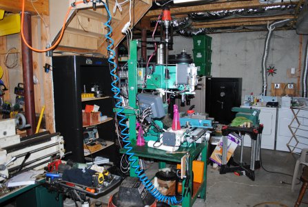
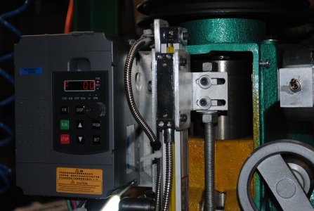
I have Ditron DROs on both my my lathe and mill and am happy with then. JeffWell the Craigslist Gods bestowed upon me this HF 33686 column mill - my first. I had used a huge Bridgeport in my youth working summers in my dad's factory so I have some experience. Came with a bunch of R8 collets, a bunch of tooling that is barely used, a so-so vise, and some other miscellaneous tooling. I have read all about the issues with Z axis control with these column mills but this is a lot more mill than I could fit into my shop space any other way.
I was wondering if moving to the use of ER32 collets instead of the R8 collets would be a good idea or not. The way I see it the process of changing these out may be simpler than dealing with the drawbar every time. Of course, my inexperience here leaves me without much to go on. Does anyone have any experience along these lines?
Also, does anyone have any advice on a not too spendy DRO for a mill of this class?
Thanks in advance
TomView attachment 378016

-
Welcome back Guest! Did you know you can mentor other members here at H-M? If not, please check out our Relaunch of Hobby Machinist Mentoring Program!
You are using an out of date browser. It may not display this or other websites correctly.
You should upgrade or use an alternative browser.
You should upgrade or use an alternative browser.
New (to me anyway) HF 33686 - my first mill
- Thread starter Tomzo
- Start date
- Joined
- Mar 3, 2020
- Messages
- 506
You’re probably doing more intricate work.
When I did this for a living I worked on heavy equipment with huge machines.
Not too much gunsight accuracy most of the time, but had to be able to do it when needed.
I did a lot of wheel centers (still do) with DRO & a rotary table.
Gonna be doing wheel center stands soon for suspension tuning on my Miata.
For lining up the head in the Z axis, I use a verticle line laser on the mill, & a plumb bob on a magnet with a string on the wall 25’ away.
With careful pre-planning on the project this is fairly accurate for me, then some fine tuning.
I am now somewhat limited with my RF31 & SB9 lathe, but am now too damn old to lift heavy equipment parts.
And I consider myself more of a welder anyway.
Cheers
- Joined
- Jul 27, 2021
- Messages
- 221
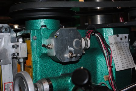
I took delivery of it late yesterday and after a long day of rearranging the shop to accommodate the mill I was beat. Upon inspection this morning I noticed that the torsion spring on the spindle was not working. I removed the spring cover to find that the spring was not connected to the shaft. It seems there is a small bolt missing that engages the spring. I presume it has a T head or something like that. I looked at the "manual" that is available online (OMG - handwritten electrical instructions??) and there is no detail on that. I was thinking that a button head screw might work, but wondered if anyone had an idea of how that assembly looks.
- Joined
- Jul 27, 2021
- Messages
- 221
This laser method seems to me to be the simplest to start out with. I am not building parts for NASA, although I will be making parts for my telescope and associated mount, focusers, etc. The way I see it is that if I plan the work carefully I can avoid changing heights. If I have to, I think that with a DRO I can set an origin with an edgefinder and then return to that after adjustment. Of course, if my origin gets machined away in the first processes it could be a problem. I was thinking of clamping something solid to the table just outside of the work area and using that as a fixed reference for adjustment after realignment.For lining up the head in the Z axis, I use a verticle line laser on the mill, & a plumb bob on a magnet with a string on the wall 25’ away.
With careful pre-planning on the project this is fairly accurate for me, then some fine tuning.
- Joined
- Apr 8, 2013
- Messages
- 1,979
For the indexing system I used a pillow block sliding on a piece of ground drill rod. It has .001 repeatability. For the head lift I used a high torque low RPM drill motor from harbor Freight. $59.00. The drill motor is connected to an ACME 10 tpi leadscrew with a tapered roller thrust bearing to take the weight. My DRO is from AMAZON and under $300.Nice! These are all things that I am considering as I go forward with this mill. If you don't mind me asking, I have seen several methods of head indexing systems - which method did you use? Also, which powered head lift system did you use?
Attachments
- Joined
- Jul 27, 2021
- Messages
- 221
Very interesting - I suppose by bypassing the stock rack for raising and lowering you bypass a lot of the torque that creates the shift anyway. I will file that idea away for a future project.For the indexing system I used a pillow block sliding on a piece of ground drill rod. It has .001 repeatability. For the head lift I used a high torque low RPM drill motor from harbor Freight. $59.00. The drill motor is connected to an ACME 10 tpi leadscrew with a tapered roller thrust bearing to take the weight. My DRO is from AMAZON and under $300.
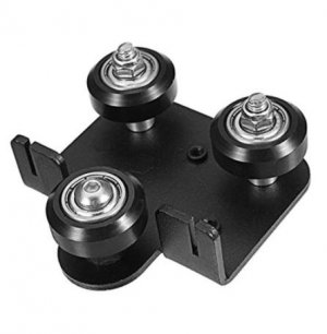
I have been looking at a bunch of the designs to reduce the shifting when raising the head, some using round stock and some square, and it got me to thinking about how 3D printers use three wheels with one with an eccentric nut to adjust the (for lack of a better word) clamping force on the rail. If one were to install a rectangular bar that has some precision and is aligned to the column, and then install a carriage similar, but larger, to the one shown here for a 3D printer, it would seem to me that it would roll up and down with a pretty high degree of accuracy. I have not seen one in a post yet - I wonder if anyone has tried this idea.
Attachments
- Joined
- Apr 8, 2013
- Messages
- 1,979
The pillow block sliding up and down the ground 7/8 inch shaft has under .001" play and the shaft can be dialed in for perfect alignment. The side shift comes from tightening the locknuts to the column but it becomes repeatable with this system. Loosening the locks moves the indicator to .005 but tightening them again brings it right back to zero. The indexing system works so well that for drilling and tapping a hole pattern or light milling in aluminum I just snug the lock lightly and don't even bother locking them down.Very interesting - I suppose by bypassing the stock rack for raising and lowering you bypass a lot of the torque that creates the shift anyway. I will file that idea away for a future project.
I have been looking at a bunch of the designs to reduce the shifting when raising the head, some using round stock and some square, and it got me to thinking about how 3D printers use three wheels with one with an eccentric nut to adjust the (for lack of a better word) clamping force on the rail. If one were to install a rectangular bar that has some precision and is aligned to the column, and then install a carriage similar, but larger, to the one shown here for a 3D printer, it would seem to me that it would roll up and down with a pretty high degree of accuracy. I have not seen one in a post yet - I wonder if anyone has tried this idea.
- Joined
- Nov 14, 2016
- Messages
- 2,999
I recently bought an ER chuck for my Grizzly copy of your machine. IMO, I prefer the R8. You have to make a wrench for a back up, and the nut wrench is fiddly and frustrating. Ymmv.
If I had it to do over again, I'd buy a set of R8 collets, and then get any additional tooling with a short straight 1/2 or 3/4" shank. Then I'd buy endmills with the same shank size. Then I'd buy screw machine drill bits. That way switching from end mill to drill bit to boring head would require no collet change and only 1-2 inches of clearance.
That is what I do with my Clausing mill, but MT2 instead of R8. I do have have some MT2 tooling, but most that I've bought is straight shank to use inthe collets. I have an ER 32 chuck for my lathe that could be used on the mill, but I haven't found a need. I guess if I needed to use something with a shank larger than 1/2" it could be useful.
- Joined
- Feb 9, 2017
- Messages
- 5,247
On my RF30 it’s hand cranking that does drifting, not the mechanism itself. It’s not hard to crank, it’s just kinda awkward.Very interesting - I suppose by bypassing the stock rack for raising and lowering you bypass a lot of the torque that creates the shift anyway. I will file that idea away for a future project.
there’s a million ways to do it. And several folks have posted great ideas. I’ve just been being careful(and lazy) but it’s not horrible to recenter either. Several years ago in a bunch of stuff out of a stop action studio where Gumby was done I got a really nice linear bearing rail and support. All I need is the bearing itself. It would be perfect for doing a similar guide like epanzella. I‘d also like to do a similar powered lift also. So many projects to triage.I have not seen one in a post yet - I wonder if anyone has tried this idea.
- Joined
- Dec 3, 2017
- Messages
- 1,909
I don't think this idea would be well received, but a coworker just drilled a hole in his vise as a permanent zero location. Raise the head, put a dowel in the collet, lower dowel into drilled hole, clamp head. He said it worked anyways.I was thinking of clamping something solid to the table just outside of the work area and using that as a fixed reference for adjustment after realignment.