Next project: Craftsman 101.07301 6" lathe

it's a spacer for the change gears
Yes it was for the 64T that goes on the end of the lead screw. There was already one on it, but as luck would have it, that one was broken so I'm glad I had it.

Only thing I got done today was to make a tailstock ram locking handle. Temperature all week has been in the 80's and next week is looking the same. "We didn't have a winter or spring. Seems to have gone straight to summer!"
 
Last edited:
FYI, to be able to do every thread on the chart, you need a total of two spacers. However, unless both are in use elsewhere, you can in some cases substitute a 20T gear or any other unused gear so long as the gear being used as a spacer doesn't touch the gear before it and/or the gear after it. But for some strange reason, the requirement to have two 9-113A spacers isn't shown on any of the parts lists that I have. However, the only places that the 10F threading chat calls out a second (SS) for Steel Spacer is for 0.005" and 0.006" feeds and for 0.5 mm pitch threads. FWIW, a 20T gear with a broken tooth (or any gear for that matter although the larger gears would take more time)) can be converted into a 9-113A by turning all of the teeth off. So if any of you have any gears with bad teeth, don't throw them away. The second spacer is often missing.
 
Seems a spacer would be a simple thing to make... you have a lathe, after all...
 
The problem is the double keyway that is required everywhere except with the screw gear, There you could get away with a single keyway.
 
By the way, that's a slick Bubba fix on the cross slide handle. Nice.

Getting close to completion. After puting the saddle assembly on the bed I found that the compound handle that I made hits the fingers due to it's closeness to the traverse handle . So I cut the outer ring off and knurled the outside of the inner ring and works quite well now. Will start working on counter-balance assembly and motor next. Waiting on three gears to arrive.
 
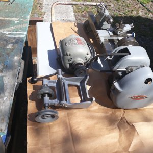
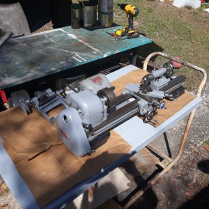
Got a little motivated and made a platform yesterday. This morning I did some layout planning and decided to put the motor on the "right" side of the counter-shaft instead of the left in order to save some footprint space. I ordered a longer belt to be able to move the motor further back away from the lathe bed.
 

Attachments

  • 20200323_120830.jpg
    20200323_120830.jpg
    2.9 MB · Views: 25
  • 20200323_114614.jpg
    20200323_114614.jpg
    4.1 MB · Views: 26
  • 20200323_114552.jpg
    20200323_114552.jpg
    4.3 MB · Views: 28
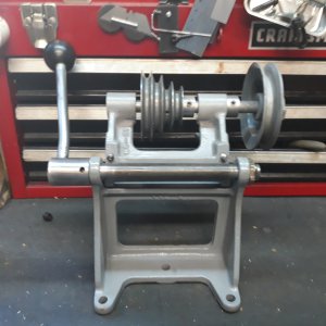
Looking at your pics i notice that the sheave on the jack shaft is a single. The original motor and jack shaft sheaves were paired double pulleys to achieve the full range of speeds for this lathe. The single speed setup should get you started, but you might want to look into getting (or making) the proper paired double sheaves. My experience is limited, but i'll bet you'll want the full range of speeds this lathe has to offer.
paulh


Got a little motivated and made a platform yesterday. This morning I did some layout planning and decided to put the motor on the "right" side of the counter-shaft instead of the left in order to save some footprint space. I ordered a longer belt to be able to move the motor further back away from the lathe bed.
 
Looking at your pics i notice that the sheave on the jack shaft is a single. The original motor and jack shaft sheaves were paired double pulleys to achieve the full range of speeds for this lathe. The single speed setup should get you started, but you might want to look into getting (or making) the proper paired double sheaves. My experience is limited, but i'll bet you'll want the full range of speeds this lathe has to offer.
paulh
The jack shaft does have the four pulley sheave on it that aligns with the headstock sheave. Or are you speaking of the pulley that is being driven by the motor? Looking at the parts list manual I don't see a double shaft sheave for the jack shaft. Yes, my motor is a replacement motor that I had laying around with no pulley so I bought pulley M6-27 single row. The double row is M6-29 and that will be up to the new owner if he wants to purchase it along with a change gear set. I think most owners never even cut threads and opt out for dies instead. Dies are so much more easy to get the job done.

On page 9 of the Speed Chart it does show a picture of a double row pulley on the jack shaft but don't see it listed, "as such", in the parts breakdown.
 
Last edited:
The motor belt pulleys are both two-step. That is how the machine gets all 16 speeds. M6-27 is the left lead screw bearing and M6-29 is the half-nut or split-nut lever. The two pulleys are M6-427 and either M6-428 (1/2" motor shaft) or M6-429 (5/8" motor shaft). Both are and always have been 2-step. The reason that the M6-427 in the illustrated parts lists only shows the larger step is that from the angle that they always seem to have been drawn you cannot see the smaller step. The early parts lists say (2 step). There are no parts lists with the later illustrated parts drawings.

Also, the slower speed settings are not just for thread cutting.

The only 6" metal-working lathes that Atlas ever built that only had 8 speeds were the MK-2's.
For my Craftsman it's kind of a moot point. Soon as it's finished it will be up for sale.
 
Last edited:
Back
Top