Numobams/Similar ELS Controller has problems

weston1968

H-M Supporter - Diamond Member
H-M Lifetime Diamond Member
Joined
Aug 29, 2016
Messages
121
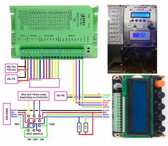
When my Numobams controller died very early I ordered a similar controller from Aliexpress. That controller worked well in forward. But when the chuck went into reverse any function that relied on the optical encoder ( chuck rotation) got lost because it could not deal with the encoder running backwards. It took awhile but I solved the problem by putting in a 4PDT switch to reverse the encoder outputs and fake the controller into thinking the lathe chuck was rotating forward. It turned out that unless I added 4.7K pullups to the A and B inputs the encoder got destroyed by the controller when flipping the forward/reverse switch ( do not know the mechanism that kills the encoder). I lost 2 encoders finding this out. I contacted the manufacturer through the sales company and they refuse to even look at the problem so I do not see it being solved. I was told that Numobams and the similar controller are both made by the same manufacturer so I expect the same problems with Numobams.

I have posted the schematic showing how to dummy the encoder to get forward and reverse working on all functions. The only thing not perfect is that in reverse LEFT and RIGHT threads are reversed.

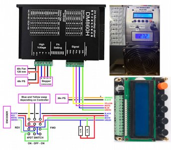
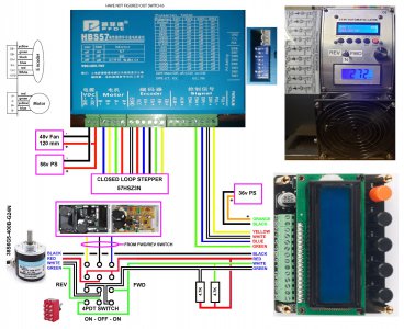
I eventually changed out the power supply to 48v, a compatible stepper driver, .and put a large 120 mm fan on the stepper to allow overdriving the current. It was needed because the stepper can lose steps if the cutter has too much resistance.

The bottom line is that I would not purchase this controller unless you feel comfortable replacing power supplies and rewiring/replacing switches. I also modified the Numobams plate to accept the original tachometer. and moved the FWD/REV switch to the plate.

In it's current state after weeks of work and extra cost I have decent operation.

The manufacturer just got back and stated that they only work with the chuck in the forward rotation for any function depending on chuck rotation.
 

Attachments

  • lead screw controlle.jpg
    lead screw controlle.jpg
    364.6 KB · Views: 74
  • lead screw controller closed loop 3.jpg
    lead screw controller closed loop 3.jpg
    452.9 KB · Views: 60
Last edited:
Had they used quadrature encoders they wouldn't have had the issue, I would think. From here, it's not possible to assess if the product is hampered by excess cost cutting, a design failure, or limited capabilities by design. Might simply be the last choice.

My ELS uses quad encoders and has no issue going forwards or backwards. It also uses a closed loop stepper. It will thread on the backside or the front side for either right hand or left hand threads. I use signed 64 bit counters for additional "protection" against roll over.

But in fairness, I have yet to implement thread to a stop yet. It's on my list of things to do. Hope to finish it this year. I'm a bit envious of that capability. I will probably use the real time feed back from the DRO's in my software to help out with that. I have instantaneous spindle angle, X and Z position to 1um, so the problem is solvable. Have some chicken scratchings, next I have to write the high level code. Surprisingly the hard part for me is simply managing the data entry. Might make a simple UI first, mimicking buttons then something nicer later.
 
The problem is not with the encoder, they used quadrature encoders. The problem is in the firmware. The manufacturer only expected the lathe to be running forward. The controller has no input telling it which direction the chuck is running so when the encoder is running in reverse the firmware get lost. The solution would have been simple, first: find out the direction of the encoder (chuck rotation direction) then swap the A and B in firmware when in reverse. This what I am doing in hardware, swapping the two phases when I switch between forward and reverse so that the firmware thinks it has forward rotation whether in forward or reverse.

When I sent the manufacturer a copy of what I was posting and explained that most people would not be interested in making all of the changes I had to make they got back to me. They acknowledged the problem and said they would fix it. I will see if they get back to me.

I just ordered:


At 4NM and closed loop I am hoping this will not drop stepper counts with heavy cutting.
 
Last edited:
If one has a quadrature encoder, it is trivial to determine direction of rotation. You don't need a hardware encoder to do this, a software encoder can figure it out. You can code it simply by knowing the following
1682189992324.png

It helps to have the edges debounced, but simply coding this will determine one direction from the other. I'm sure there are Arduino libraries that will do this for you including the debounce. I use a library for my ELS, and it has NO issue determining direction and runs up to 250 KHz, which is the limit of my encoder output..

I've also used a simple state machine to determine direction (but it didn't have de-bouncing) which worked almost all the time. Because it failed every once in a while, that's why I ended up using a library that de-bounces A and B and then decodes it.

For my ELS, I bought this: https://www.ebay.com/itm/333996572703 and have been very happy with it. In my opinion, the eBay unit is better, in that it comes with all the cables, and the correct power supply for only $3 more. If you only need the motor and driver, you can find this same unit for less money. Good luck!
 
I agree about the decoder. The problem is their software was only expecting it to run in forward. When it ran in reverse and the phases were backwards from what they expected they got lost. By swapping the phases in hardware, I gave the software what it expected and it was happy. I must have sent 20 emails before my explanation got through to the manufacturer. This works for all functions, but when cutting threads LEFT is RIGHT and RIGHT is LEFT.

I used a 48v supply on my 556 driver which was also a 50v unit. for about a week then when it was powered but not even running I heard a bang and it was dead. I opened it and a capacitor in the power section exploded. I am going to use 40v on my setup.

I like the cabling much better on your motor.
 
Last edited:
This works for all functions, but when cutting threads LEFT is RIGHT and RIGHT is LEFT.
I have to laugh, as I spent a lot of time trying to get that correct. Finally got it to work after a half a dozen tries! Simply was confusing working through all the cases, for right hand and left hand threads, both towards the chuck and away from the chuck. Think I got it. Had to run a lot of tests to confirm the operation... I had to install a marker in place of a cutter tool, to confirm I got the handedness of the threads correct for all the configurations. Then I stared at the lines on the stock, to make sure they were correct. The slope of the lines tells you if you got the right hand/left hand thing correct, as long as you use a consistent view point!

Seem the Numobam's attempt was not fully thought through. That's a shame, since it was almost a really great thing. A good idea, but slightly under engineered.

The CL57T closed loop driver is quite good. I am using it at 48V. The higher voltages do give you more torque. I have experienced exploding electrolytic capacitors before, and it sure scared me when one ruptured it's case. That was on a computer mains power supply, and the noise was really loud. So I don't blame you for backing off the supply a bit. That being said, I have used the CL57T for 6 months at +48V without a issue. When I disassembled the CL57T, it appeared to be very well made inside, better than I expected. I did buy the unit from Steppers Online.
 
Last edited:
I like Steppers Online. I would have bought from them if I had know about it. I have purchased a few steppers from them in my lathe pursuit and always been happy.

Thanks for pointing me in this direction..
 
Voltage equates to speed because the higher the voltage the faster the rate of rise of current through the motor inductance. Current equates to torque. Force is proportional to ampere turns.
 
I got my Nema 24 motor in and went to mount it and discovered that not all Nema 24 motors have the 47.14 distance between mounting holes that the spec has. The motor I got in was 50.00 between centers. Had to return it and the only Nema 24 I could find with the right centers was only 3 NM. I ordered a Nema 23 with 3 NM but will take higher voltage. I have found that the smaller the motor the faster it will run. I am going to try and find the torque curves. Attached is the schematic of what would have been.

Nema 23 ordered: https://www.amazon.com/gp/product/B09TQRT1GT/ref=ppx_yo_dt_b_asin_title_o00_s00?ie=UTF8&psc=1
 

Attachments

  • lead screw controller closed loop.jpg
    lead screw controller closed loop.jpg
    386.6 KB · Views: 54
Back
Top