Pantograph machine

Sparweb

Registered
Registered
Joined
Aug 23, 2020
Messages
55
It's the strangest thing. Think "Hand-held NC"

A friend of mine gave me the parts of the machine last year. He didn't know what to do with them, and there certainly were some confusing parts until I started to put it together. Once I had it figured out, I started to find ways to make it work better. Here's where I'm at right now:

Duplicating a 2-D shape in aluminum:

Duplicating a 3-D shape in wood:


The biggest puzzle was figuring out how to set up the wheels on the track, and keep them moving freely, while preventing any twist that would allow one wheel to turn faster than the other. These wheels just travel freely, so it turned out to be as simple as locking the axle to the wheels. Strangely, that WASN'T how it was originally assembled, but maybe some strange stuff happened before it came to my hands.
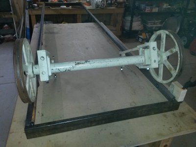
20200521_195031_axle.jpg

Here's what it's supposed to look like from the manufacturer (the product is discontinued). http://www.terrco.com/woodcarvers/kstar.php
Gun stocks and duck decoys are just the beginning!!

The original came with a 4' long bed. I've built a bed that's 12 feet long instead. It's on a table and soon I'll be setting up the table for work-holding.
 
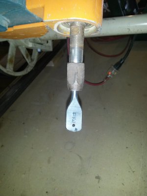
The current puzzle is tool-holding. Here's what it's got now:

20200603_171952_cutter.jpg

That's a modified spade-bit for very aggressive cuts. I tried it in soft wood, but I won't do that again. The videos were made with a 1/4" straight-edge bit which works much more sensibly. What you can also see in the picture above is the holding device for the cutter. Not very fancy. The threaded shaft is bored through 1/4" very roughly, and slotted so that when the nut is tightened, it closes the "fingers" on the tool. Yeah, inspired by tool collets, but doesn't work as well as they do. I stopped using this router when a bit worked its way out and flew across the room.

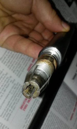
Here's why.

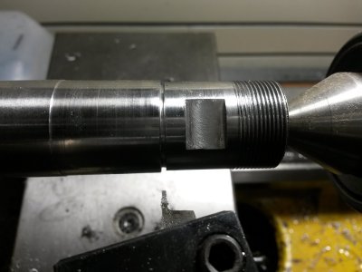
20201109_221943_shaft.jpg

Rust, scoring, and then the threads started to strip. Tight enough to strip the thread isn't tight enough to retain the cutter.

So I need a new way to hold the cutters...
 
So over the weekend, I started planning an adapter to allow it to hold ER16 collets.
I'd have to turn down the end of this shaft to fresh metal first, then make a pair of mating ends so that I can attach an adapter to hold collets.

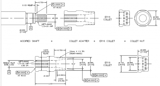
The SOWA website is great, because they have DXF files of their tool-holders. I can come up with the dimensions from their drawing for the adapter to hold an ER16 collet.

Arbor-2020-11-08.PNG

Has anyone tried making adapters for ER16/20/etc. collets?
I've been guessing on the tolerances... struggling to figure out how to represent what I mean, in fact. I'm not well practiced in GD&T, but it really seems appropriate for this part.
The goals are to make an adapter that maintains enough concentricity that it can turn 12,000 RPM (the speed of the router).
I'm also hoping to make the adapter fit both the collet and the nut - minimizing the special parts to just 1.
On the router, you can see 2 cutter heads. One turns CCW and the other turns CW. So the mating thread of the adapter will be RH on one side, and LH on the other side.
 
Are you depending on the threads of the modified shaft and the adapter to hold concentricity? Might not work, because you always need some clearance between male and female threads. Possibly add a "register" feature to the end of the adapter that centers on the diameter of the "modified shaft."

PS - minor nit to pick - the ER thread is 1.5mm pitch, not 1/5 TPI :)
 
@hman,
Probably right. Another friend of mine has looked at this drawing and said the same thing. What makes it worse is that he would probably use a tap to make the inside thread. Kiss concentricity goodbye.

He has come up with some interesting ideas to substitute the existing bearing with a larger one. Having a larger bore permits the shaft itself to hold the collet, and we can make a new shaft to do it.
 
We have made some progress with the pantograph/duplicating machine.

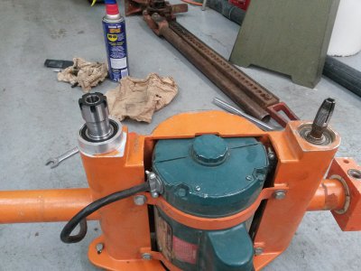
We have the first of the new shafts test-fit to confirm the dimensions, particularly length between end bearings, is correct.
That's an ER20 collet, by the way. We figured out a way to adapt a larger bearing. The shaft we have in now doesn't match the diagram I posted last month.
It took a while for my and my friend to come to terms about the nuts on some ER collet systems. Below is a "mini-nut" completely different from the standard nut. I really wanted to use a mini nut but he has a set of ER20 collets for his milling machine with standard nuts. The nuts are not interchangeable so the collet holding thread has to be made for the nut you choose. Once that was sorted out a lot of dimensions revolved around the 24mm thread and fitting a 25mm ID bearing.

The shaft isn't finished yet. Missing a circlip and wrench flats to tighten it up. But really close now.

Duplicator Test Fit Shaft 20201211_165313_S.jpg
 
Success!
My friend finished the second shaft and also gave me a third "spare" which he thought he screwed up but the mistake turned out to be negligible.
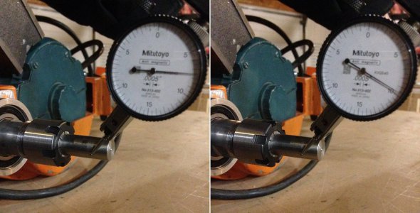
Last night I got the second shaft installed and checked for runout. The two shafts are 0.002" and 0.001" respectively. I'm impressed already.
Final_runout_0.002 - Copy.jpg
 
With test fits done, there were some last steps do be finished up on the shafts - snap-ring grooves principally. If things hadn't fit properly I had expected to shorten up a shoulder here or there. Turned out to be fine.

It's a wee little cutting tool for them snap rings...

20201223_162051 - SnapringGroove.jpg
 
Now, the next thing to do is mount the duplicator on the framework, like it was before.
I will also need to start buying collets and cutters!

The neat trick with this machine is that the two cutting heads counter-rotate. This cancels cutting forces and there's no kick when you start the motor, either. It handles really nice when you're cutting with it. I was able to use it for a few pieces before I discovered the problem with the original chucks. I'm hoping to get back to cutting pieces soon.

It's probably a bad time to be ordering tools and stuff on Amazon!
 
Interesting that they counter-rotate. One cutter will be "climb milling" while the other is "normal milling." Plus you can't use normal router bits for both :(
I was interested in just how the counter-rotation is driven, but couldn't find it in a cursory re-read. Is it done with belts?
 
Back
Top