Placed First Order With Enco

I received the first part of my order with Enco yesterday, which is pretty astonishing, really, since I had just placed the order at about 10:30PM Wednesday night. Anyway, in this first shipment I received the Phase II QCTP I ordered.

I opened the box to check it out. The question that first came to my mind was about the "T-nut" that comes with it and needs machining in order to fit the slot on my tool post. It's just a flat hunk of steel. That's not my concern as that is what I expected. My concern has to do with the size of it. I measured it with a ruler and it isn't even 1/2" thick. It's close to 1/2", but it seems like it may be just a little less, maybe a metric size.

Anyway, is that all it's supposed to be (in regard to thickness)? When I measured my tool post, from the bottom flat to the top, I measured a depth of 5/8" (.625). Since this hunk of metal is only 1/2", by the time I machine the "T" engagement for the slot, that would only end up allowing about 3/16" of engagement in the upper slot portion. Is that enough? Honestly, I sort of assumed that the block of steel to machine the t-nut would have been thicker than the 5/8" total depth of the tool post slot. Is this the block size that they always have included with their QCTPs? Or, did it used to be larger and they have cut costs now? Just curious.
 
If you are worried about the block of steel not being tall enough just go buy a dollar scrap of CRS or 4140 and mill one down to size you want. FWIW on one of my lathes the t nut is short of top of slot by a good amount and the set up has worked fine for 13 years. The important feature for good holding is a flat surface for the toolpost to sit on with no burrs on either mating surface. I suspect you will be fine with the material provided but if not, make your own as tight a fit as you feel is necessary.

cheers
michael
 
I've purchased a similar QCTP. It had a similar chunk for the T slot, and has worked perfectly well.

Think about the forces being applied. The main one is the stud pulling the T nut upward as the QCTP is held to the top of the compound. This force has to be spread to the undersides of the T slots. Even ⅜" steel would be plenty strong for this task. The fact that the T nut's top is lower than the top of the compound is not only OK, but necessary. If it were even with the top or higher, the QCTP would bottom out on the nut instead of being held against the top of the compound. The engagement between the T nut and the upper slot portion doesn't see any force. It's just there to keep things lined up when the stud is loosened and the position of the QCTP is adjusted. Even a slight engagement would be OK, as long as there's still engagement when the stud very loose and the T nut rests on the bottom of the slot.
 
Thanks for the advice guys. I get and concur with your explanations. It does make sense. I could make one with a piece of flat stock I have around the garage, but I'll work with the one that came with the post first and see how that comes out. BTW, I get why the t-nut shouldn't protrude above the top of the compound. I always understood that. If the block of steel that came with the QCTP was 5/8" thick, I would have at least machined off some number of thousandths to make sure it was some amount below even with the top. :D
 
I've purchased a similar QCTP. It had a similar chunk for the T slot, and has worked perfectly well.

Think about the forces being applied. The main one is the stud pulling the T nut upward as the QCTP is held to the top of the compound. This force has to be spread to the undersides of the T slots. Even ⅜" steel would be plenty strong for this task. The fact that the T nut's top is lower than the top of the compound is not only OK, but necessary. If it were even with the top or higher, the QCTP would bottom out on the nut instead of being held against the top of the compound. The engagement between the T nut and the upper slot portion doesn't see any force. It's just there to keep things lined up when the stud is loosened and the position of the QCTP is adjusted. Even a slight engagement would be OK, as long as there's still engagement when the stud very loose and the T nut rests on the bottom of the slot.

A reassuring thought is to consider that the strength of the thread engagement of the stud is far less than everything else.
 
I have a Grizzly 10 x 22 lathe, and I ordered a Bostar QCTP from Ebay. It came with a short thick plate that would have to be machined down to fit the slot like yours. I found another solution from another forum. I bought an extra plate from Grizzly like the one that came with the turret tool holder, and then drilled and tapped it to fit the QCTP bolt.

It worked well, and since I didn't have a mill at the time was the only solution available. Total money: $4.00 for the plate, another $10 or so for the tap. And if I need the turret tool holder for some job, it's still got the original plate.

Of course, I have since purchased a mill, so now I could make my own plate or mill the thick one to the correct size.
 
I started work on making a t-nut for my compound slot. I decided to make my own instead of using the one that came with the Phase II QCTP. It's really not so much that I don't believe the one that came with the tool post will work. I'm sure it will. I figured it would be a good project for me to get used to this lathe and see what I can do with it and how accurate it can be.

I machined a rectangular block out of some steel I had using the 4-jaw chuck. After some fiddling around, it turned out very well. I machined the height to 1/32" less than the overall depth of the compound to make sure it would secure the QCTP properly. Now I'm contemplating how I want to mill the two edges off. I bought an angle plate from ENCO on the order I just placed along with a couple t-slot nuts to secure it to the compound. That's done. I had to made some shims up in order for the bottom of the angle plate to clear the radius of the compound. I'm messing around with how I want to control the z-axis, up/down dimension. I think that's "z" anyway. I mounted a parallel onto the angle plate that the block I made will locate against. I'll indicate the surface of the plate to make sure it's square in two planes to the spindle and then I'll indicate the parallel I mounted to the angle plate to make sure it's level (relative to the chuck). I'm going to locate the parallel on the angle plate by resting the block against it and bringing the entire apparatus down until the block is just touching the end mill. Then, in order to advance (downward) the block the correct distance for milling, I'll make up a shim to place between the parallel and the block.

Sound like too much? I think it will work. Comments? Suggestions?

I'm waiting to do the milling until I drill and tap the 14mm hole into the center of the block. I had to order the tap locally and it should be in this week. I want to use the hole to help secure the block to the angle plate along with 2 finger clamps that I also purchased from ENCO on last order.

Once I get the entire apparatus set-up, I'll take some pictures and post them along with a description. If this works, it would be a very economical way to machine this t-nut (along with other basic milling). The small angle plate was on sale, I already had the parallels, some screws to mount it, some cheapo ENCO t-nuts and finger clamps. The tap was the most expensive part of this operation. Maybe someday I'll get ambitious and make a nice milling attachment, better than the Atlas ones that can be purchased. Anyone ever make a milling attachment for their lathe?
 
This post is only geared towards those without a milling machine, like me, and who may be unsure of how to make a t-nut to fit their compound using a lathe and for relatively little expense. I know there's another "how-to" somewhere on Hobby-Machinist about machining the entire t-nut in a chuck, but I didn't see one for setting up a milling operation on the compound without using a milling attachment. For those who may want to make a t-nut on their lathe to mount a QCTP, I thought I'd share this inexpensive jig I made up to do so. I don't have a milling attachment (yet, but would rather get a mill)), so I had to come up with something accurate and cheap.

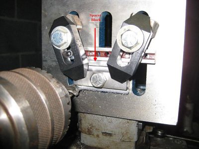
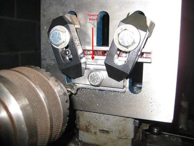
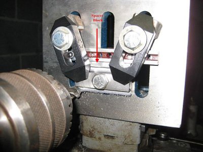
The first thing I did was buy an angle plate. I ordered from ENCO. The plate was on sale and I got another 20% off and free shipping. I think I spent like $12 for it or something. I also purchased a 1/2" end mill, a couple tee-nuts, and a couple strap clamps. Somewhere around $20 for the entire setup. Maybe $22. And I will be able to use the angle plate for other things such as on my drill press. I think it's a good investment. I may even do some other small milling jobs in the lathe. Anyway, here's a picture of the setup:

T-Nut%20Milling%20Setup_zpsidwrnmwi.jpg

I made a block to size in the lathe using the 4-jaw chuck, all six sides, square and parallel. Second, I centered the block in the 4-jaw and drill and tapped the 14mm hole because I wanted to use the hole to help secure the block to the angle plate. I then mounted the angle plate to my compound with the tee-nuts I bought. I had to do some minor handwork on them to get them to fit the compound slot. I indicated the angle plate to ".000" in two planes. I then took the block and c-clamped it against the parallel. I lowered the parallel/block assembly onto the end mill in the chuck, so that the block was just resting on the end mill. I then moderately tightened two screws that I had securing the block to slots in the angle plate. I then stuck an indicator in the chuck and indicated the block square to the chuck and tightened up the screws securely holding the parallel.

From calculations based on the dimensions of the t-slot in my compound, and the dimensions I made the t-nut to (tight fit), I was able to calculate that if I made a spacer that was .206 in thick, and placed it between the parallel and the t-nut, that would drop the t-nut the appropriate amount to machine the corner off the raw block and make it into a t-nut. I stuck the spacer between the parallel and block and then added another bolt through the hole in the block to help secure it. I added strap clamps for more rigidity. Depth was controlled by an indicator on the backside of the carriage. I took off about .020" - .030" in at a time. Doing the other side was as easy as flipping over the t-nut.

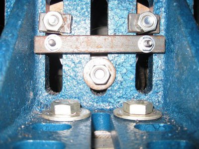
Here's a picture of the backside of the angle plate.

Rear%20Of%20Milling%20Setup_zpszdnphogb.jpg

That's it. Cheap and dirty.

T-Nut%20Milling%20Setup_zpsidwrnmwi.jpg

T-Nut%20Milling%20Setup_zpsidwrnmwi.jpg

Rear%20Of%20Milling%20Setup_zpszdnphogb.jpg

Rear%20Of%20Milling%20Setup_zpszdnphogb.jpg
 
Is that drill chuck attached to your spindle with a taper and drawbar?
 
No. It's a headstock spindle chuck. It screws onto the spindle thread. Came with the lathe. I checked the runout when I put it on and it's darn near .000. Maybe a couple ten thousandths, and that's maybe. The end mill ran very true. It's pretty heavy-duty. Pretty old. I know that's not the most ideal way to hold an end mill, but had to use what I had since I haven't gotten a collet chuck, yet, for the lathe. All in all it worked out well. I'd have no issue with using it again to hold an end mill if I ever do any more milling on the lathe.
 
Back
Top