
Typo: registration pin item 13.A quick look: It looks like the taper unit is bolted to the back side of the carriage. Unite 14 is bolted with items 12. PM does not use registration pins, item 12.
The bad news is that on careful observation, item 14 seems to slope down from the back of the carriage. How can that be? I'll have to indicate some machined horizontal surface of item 14.
On a quick look it looks like the taper unit was mounted onto a painted surface. I'll have to check that out tomorrow, but if so, it is not surprising that during shipment, the unit would have crushed the paint and thereby settled in a slope: the axis of the cross slide screw and the unit then would not be colinear and the bearing that is housed in item 14 would not be perpendicular to the axis of the cross slide screw.
I hope mine is the only one that is like this. Others who have the taper unit might see if it was mounted over a painted surface.

-
Welcome back Guest! Did you know you can mentor other members here at H-M? If not, please check out our Relaunch of Hobby Machinist Mentoring Program!
You are using an out of date browser. It may not display this or other websites correctly.
You should upgrade or use an alternative browser.
You should upgrade or use an alternative browser.
PM-1660TL
- Thread starter erikmannie
- Start date
- Joined
- Sep 8, 2019
- Messages
- 4,392
Thanks. I read the manual. It was a good decision to have them install it. I am reading the manual again now, to learn the names of the parts, etc., before calling PM. The cross slide wheel is hard to turn with the taper unit disengaged.
I also thought something was binding or out of alignment, yesterday, and took off the cap to see what's under the hood:
View attachment 376227
In the process I stripped one phillips head screw top and had to hammer it free with a pick: They were really jammed in at PM. I'll be replacing the 5mm 0.8 with star screws, so that next person will be able to open it. There is a bearing there:
View attachment 376234
I'm keeping my fingers crossed that is not the the problem.
Another member here, @erikmannie who received a 1640TL with a pre-installed taper unit was also having problems with a tight cross slide. I wonder if he resolved his problem.
Thank goodness for this community.
I never had a problem with a tight cross slide. PM installed the taper attachment, & the cross slide handwheel had the proper resistance.
I said that I *like* a tight cross slide. I mistakenly (!) used the cross slide backlash adjustment screws to (1) serve as a cross slide lock (because my DRO scale cover is blocking the cross slide lock screw), as well as (2) increase the resistance in my cross slide handwheel (because I was too *lazy* to tighten the gibs).
I work such long hours that I only have about 6 hours/week to work in my shop. I get 6 weeks vaca per year, & then I get a LOT of shop time. When I retire in 9 years, I will really get a lot of shop time. As such, I sometimes take unwise shortcuts & am often a bad example of somebody who uses best practices.
Last edited:
The stiff cross carriage wheel problem was solved. As delivered, I had to use two hands to turn the cross slide wheel.
PM suggested that I look at the junction of the taper unit and the back of the carriage. They are joined by four bolts, items 12 in the following diagram.

When I loosened these bolts, I could use a home made portable gantry to pull the unit up. There was about 0.010 inch looseness, up and down. There is horizontal play also, but I did not pay attention to that. I tried random positions until I found a position that gave me the loosest cross slide action. It is still tight, but at least I can turn the wheel with one hand, now.
There is a need for some mechanism, a jack, or cam, so that the taper unit can be placed at a specific place. (PM does not use the registration pins, item 13.) Maybe when I get the mill installed .... Bolting a heavy taper unit onto a painted surface is not a long term solution.
When I did the above, the four bolts 103 and the set screw 102 (from another diagram that details just the cross slide) at the center of the cross slide were all loosened. Also the gib was loosened. Those screws and the gib are now adjusted properly.
To get to the taper unit, I removed the back splash guard. A home made gantry was used to gently pull up on the splash guard and then I removed three bolts. The direct access from back of the machine enabled me to see much more that had to be cleaned.
Also, I could see the damage that the deadman clamp item 50 did when the taper unit was disengaged, as suggested, by loosening bolts 49, and thereafter the carriage moved. I intend to remove the whole of item 50 and the arm 45, when the taper unit is not in use.
Thank goodness for paint matching technology: the scratches can be covered up with a little paint.
So, when all the manual controls were confirmed ok, I placed the lathe fully on one concrete slab in the garage. It is square with the grid of the concrete slabs, within about 5 mm. I leveled it as best as I could, better than 1/2 of a thick on a machinist level. I had to iterate a dozen times, because adjusting one leveling bolt ... you know the story. I'll check the level again in the morning. The floor falls away enough that I had to put a 3 by 4 inch, 1/2 inch steel plates underneath each of the two leveling pads on the tail stock side.
Next: I have to use the VFD to convert single phase to 3 phase. My plan is to have the unit do just that. All the fancy stuff can come later. The goal is just 60 Hz, 3 phase, 240V (or whatever the actual voltage is in the house: the VFD does not pump up the voltage, and the output voltage cannot be higher than the input).
Then, I can brake-in the machine and get advice from the pros when to change the oil.
PM suggested that I look at the junction of the taper unit and the back of the carriage. They are joined by four bolts, items 12 in the following diagram.
When I loosened these bolts, I could use a home made portable gantry to pull the unit up. There was about 0.010 inch looseness, up and down. There is horizontal play also, but I did not pay attention to that. I tried random positions until I found a position that gave me the loosest cross slide action. It is still tight, but at least I can turn the wheel with one hand, now.
There is a need for some mechanism, a jack, or cam, so that the taper unit can be placed at a specific place. (PM does not use the registration pins, item 13.) Maybe when I get the mill installed .... Bolting a heavy taper unit onto a painted surface is not a long term solution.
When I did the above, the four bolts 103 and the set screw 102 (from another diagram that details just the cross slide) at the center of the cross slide were all loosened. Also the gib was loosened. Those screws and the gib are now adjusted properly.
To get to the taper unit, I removed the back splash guard. A home made gantry was used to gently pull up on the splash guard and then I removed three bolts. The direct access from back of the machine enabled me to see much more that had to be cleaned.
Also, I could see the damage that the deadman clamp item 50 did when the taper unit was disengaged, as suggested, by loosening bolts 49, and thereafter the carriage moved. I intend to remove the whole of item 50 and the arm 45, when the taper unit is not in use.
Thank goodness for paint matching technology: the scratches can be covered up with a little paint.
So, when all the manual controls were confirmed ok, I placed the lathe fully on one concrete slab in the garage. It is square with the grid of the concrete slabs, within about 5 mm. I leveled it as best as I could, better than 1/2 of a thick on a machinist level. I had to iterate a dozen times, because adjusting one leveling bolt ... you know the story. I'll check the level again in the morning. The floor falls away enough that I had to put a 3 by 4 inch, 1/2 inch steel plates underneath each of the two leveling pads on the tail stock side.
Next: I have to use the VFD to convert single phase to 3 phase. My plan is to have the unit do just that. All the fancy stuff can come later. The goal is just 60 Hz, 3 phase, 240V (or whatever the actual voltage is in the house: the VFD does not pump up the voltage, and the output voltage cannot be higher than the input).
Then, I can brake-in the machine and get advice from the pros when to change the oil.
- Joined
- Sep 8, 2019
- Messages
- 4,392
The stiff cross carriage wheel problem was solved. As delivered, I had to use two hands to turn the cross slide wheel.
PM suggested that I look at the junction of the taper unit and the back of the carriage. They are joined by four bolts, items 12 in the following diagram.
View attachment 376325
When I loosened these bolts, I could use a home made portable gantry to pull the unit up. There was about 0.010 inch looseness, up and down. There is horizontal play also, but I did not pay attention to that. I tried random positions until I found a position that gave me the loosest cross slide action. It is still tight, but at least I can turn the wheel with one hand, now.
There is a need for some mechanism, a jack, or cam, so that the taper unit can be placed at a specific place. (PM does not use the registration pins, item 13.) Maybe when I get the mill installed .... Bolting a heavy taper unit onto a painted surface is not a long term solution.
When I did the above, the four bolts 103 and the set screw 102 (from another diagram that details just the cross slide) at the center of the cross slide were all loosened. Also the gib was loosened. Those screws and the gib are now adjusted properly.
To get to the taper unit, I removed the back splash guard. A home made gantry was used to gently pull up on the splash guard and then I removed three bolts. The direct access from back of the machine enabled me to see much more that had to be cleaned.
Also, I could see the damage that the deadman clamp item 50 did when the taper unit was disengaged, as suggested, by loosening bolts 49, and thereafter the carriage moved. I intend to remove the whole of item 50 and the arm 45, when the taper unit is not in use.
Thank goodness for paint matching technology: the scratches can be covered up with a little paint.
So, when all the manual controls were confirmed ok, I placed the lathe fully on one concrete slab in the garage. It is square with the grid of the concrete slabs, within about 5 mm. I leveled it as best as I could, better than 1/2 of a thick on a machinist level. I had to iterate a dozen times, because adjusting one leveling bolt ... you know the story. I'll check the level again in the morning. The floor falls away enough that I had to put a 3 by 4 inch, 1/2 inch steel plates underneath each of the two leveling pads on the tail stock side.
Next: I have to use the VFD to convert single phase to 3 phase. My plan is to have the unit do just that. All the fancy stuff can come later. The goal is just 60 Hz, 3 phase, 240V (or whatever the actual voltage is in the house: the VFD does not pump up the voltage, and the output voltage cannot be higher than the input).
Then, I can brake-in the machine and get advice from the pros when to change the oil.
I wouldn’t worry about the paint at all. Once you use the machine a bunch, some paint will inevitably flake off. It doesn’t matter because you will hopefully have a film of way oil (or oil-based cutting fluid) on all of the surfaces which are vulnerable to corrosion.
It would be a frustrating existence to keep it looking new, but you can easily keep it oiled & thus safe from corrosion.
I *really* enjoy cleaning a machine tool; I find it very therapeutic.
It's the 'new car and its first scratch' syndrome. You, know, you get a new car; when you see that some one has dinged your new car, the zing echoes through out the body. Then after some months, the next ding isn't even noticed.I wouldn’t worry about the paint at all. Once you use the machine a bunch, some paint will inevitably flake off. It doesn’t matter because you will hopefully have a film of way oil (or oil-based cutting fluid) on all of the surfaces which are vulnerable to corrosion.
It would be a frustrating existence to keep it looking new, but you can easily keep it oiled & thus safe from corrosion.
I *really* enjoy cleaning a machine tool; I find it very therapeutic.
I never paid attention to scratches, chips, ding, even damage from crashes on club machines, or friends machines. But when I saw the little dings on the tail stock on a brand new machine, I went and got a pint of matched paint. It's not a perfect match, but I haven't noticed where the ding had been since I used the touch up paint on the spot. Then, today, when I removed the splash guard and saw the damage that the dead man clamp did, I thought, well I still have a pint of matching paint. And moved on.
Anyway, I was too busy using both hands to turn the cross slide wheel! LOL Boy am I glad that's solved, sort of.
On to the next rabbit hole !
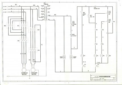
In the electrical control and distribution box of the PM-1640TL there was a document describing the electrical system. If anyone has an official electronic copy of it, I would appreciate it if you would post it. Thank you.
In the mean time, I scanned the document and here it is.


Observe "Sheet 2 of 1". So, it was an oriental language speaker that drew the circuits. In some of the oriental languages, the thought process is: "of 2 parts, this is the first".
The diagram is in unfamiliar notation to me. It does not use symbols used in the Pm-1440GT nor the Pm-1340GT documentation of the electrical system.
If these symbols are part of some standard, please let me know, so that I can be sure of the circuit. As it is, I will try to make sense of each symbol first, then, segment the drawing into independent parts: that will make understanding the critical circuit, the safety part of the system, easier to understand.
Wires are numbered with plain numerals, and some wires are labeled with a letter. As I try to explain the circuit to myself, I will use w3 for wire 3 and w11 for wire 11, and so on. An alpha lettered line is its function, not a single piece of wire. Hence wires labeled R are in several locations, indicating the function of that part of the circuit, not a continuous piece of wire.
K1, K2, K3, K4 are relays. The description does not detail to which pin of the relay a wire is attached, only that it is associated with a relay. The relay contacts are represented by what in standard electronics circuits would be a capacitor: like two capital T facing each other, as between w6 and w10.

Normally closed (connected) but opened (disconnected) by energizing the coil is represented by the contact symbol with a stroke across it, as in the symbol between w10 and w12.

The alternating current coil is represented by what electronics engineer would associate with a signal source: a squiggle in a circle, as in the symbol between w12 and [w3-1]. K1 says it is the coil associated with relay 1.

Switches are represented in several ways. There is a single pole, single throw switch SW1 between w2 and w8. It is a simple connect or disconnect switch.

The switch between w0 and w1 is a limit switch. When the end cover pushes up against a roller arm of the switch, the circuit closes (connects).

The switch LS3 and LS4 between w4 and w5 are each a switch that disconnect one circuit and connects to another circuit. In combination, they are part of an either or logic circuit. The switches are physically placed near a cam such that only one switch is active. They are use in the safety component of the lathe is discussed below.

There is a push to disconnect switch, SPB1, between w1 and w2.

There is a push to connect switch, PB1, between w2 and w6.

There are several functions in the diagram. Each function will be discussed, going from left to right:
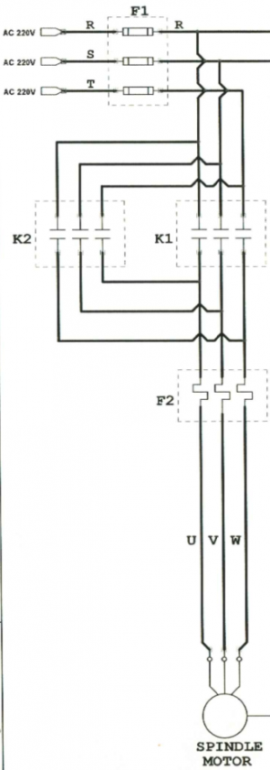
1. Three phase, 220V power, on wires R, S, and T, common 220V designation, is connected to the motor via fuses F1, two relays, K1 and K2. Either K1 or K2 is activated at any time. This function is assured by the physical switch positions, which allows only one of LS3 or LS4 to be active, and further relay logic. Damage to the switches, or displacement of the switches could lead to an error in this critical function. The circuit at the far right (discussed later) ensures that only one K1 or K2 is activated at any time. When K2 is active, S and T are interchanged resulting in the motor reversing direction. There is another set of fuses, F2, just after the relays. At the motor, the power from R, S, and T is delivered to U, V, W, which is common designation for wires leading out of a three phase motor.

2. Second section of the circuit from the left routes 220V power to the coolant. Relay K3 connects power from R and S to U1 and V1.

[ I ran into a limit of 20 attachments So, this discussion will continue in the next post. ]
In the mean time, I scanned the document and here it is.
Observe "Sheet 2 of 1". So, it was an oriental language speaker that drew the circuits. In some of the oriental languages, the thought process is: "of 2 parts, this is the first".
The diagram is in unfamiliar notation to me. It does not use symbols used in the Pm-1440GT nor the Pm-1340GT documentation of the electrical system.
If these symbols are part of some standard, please let me know, so that I can be sure of the circuit. As it is, I will try to make sense of each symbol first, then, segment the drawing into independent parts: that will make understanding the critical circuit, the safety part of the system, easier to understand.
Wires are numbered with plain numerals, and some wires are labeled with a letter. As I try to explain the circuit to myself, I will use w3 for wire 3 and w11 for wire 11, and so on. An alpha lettered line is its function, not a single piece of wire. Hence wires labeled R are in several locations, indicating the function of that part of the circuit, not a continuous piece of wire.
K1, K2, K3, K4 are relays. The description does not detail to which pin of the relay a wire is attached, only that it is associated with a relay. The relay contacts are represented by what in standard electronics circuits would be a capacitor: like two capital T facing each other, as between w6 and w10.
Normally closed (connected) but opened (disconnected) by energizing the coil is represented by the contact symbol with a stroke across it, as in the symbol between w10 and w12.
The alternating current coil is represented by what electronics engineer would associate with a signal source: a squiggle in a circle, as in the symbol between w12 and [w3-1]. K1 says it is the coil associated with relay 1.
Switches are represented in several ways. There is a single pole, single throw switch SW1 between w2 and w8. It is a simple connect or disconnect switch.
The switch between w0 and w1 is a limit switch. When the end cover pushes up against a roller arm of the switch, the circuit closes (connects).
The switch LS3 and LS4 between w4 and w5 are each a switch that disconnect one circuit and connects to another circuit. In combination, they are part of an either or logic circuit. The switches are physically placed near a cam such that only one switch is active. They are use in the safety component of the lathe is discussed below.
There is a push to disconnect switch, SPB1, between w1 and w2.
There is a push to connect switch, PB1, between w2 and w6.
There are several functions in the diagram. Each function will be discussed, going from left to right:
1. Three phase, 220V power, on wires R, S, and T, common 220V designation, is connected to the motor via fuses F1, two relays, K1 and K2. Either K1 or K2 is activated at any time. This function is assured by the physical switch positions, which allows only one of LS3 or LS4 to be active, and further relay logic. Damage to the switches, or displacement of the switches could lead to an error in this critical function. The circuit at the far right (discussed later) ensures that only one K1 or K2 is activated at any time. When K2 is active, S and T are interchanged resulting in the motor reversing direction. There is another set of fuses, F2, just after the relays. At the motor, the power from R, S, and T is delivered to U, V, W, which is common designation for wires leading out of a three phase motor.
2. Second section of the circuit from the left routes 220V power to the coolant. Relay K3 connects power from R and S to U1 and V1.
[ I ran into a limit of 20 attachments So, this discussion will continue in the next post. ]
Attachments


This is a continuation of posting #616.In the electrical control and distribution box of the PM-1640TL there was a document describing the electrical system. If anyone has an official electronic copy of it, I would appreciate it if you would post it. Thank you.
In the mean time, I scanned the document and here it is.
View attachment 376536
View attachment 376537
View attachment 376541
Observe "Sheet 2 of 1". So, it was an oriental language speaker that drew the circuits. In some of the oriental languages, the thought process is: "of 2 parts, this is the first".
The diagram is in unfamiliar notation to me. It does not use symbols used in the Pm-1440GT nor the Pm-1340GT documentation of the electrical system.
If these symbols are part of some standard, please let me know, so that I can be sure of the circuit. As it is, I will try to make sense of each symbol first, then, segment the drawing into independent parts: that will make understanding the critical circuit, the safety part of the system, easier to understand.
Wires are numbered with plain numerals, and some wires are labeled with a letter. As I try to explain the circuit to myself, I will use w3 for wire 3 and w11 for wire 11, and so on. An alpha lettered line is its function, not a single piece of wire. Hence wires labeled R are in several locations, indicating the function of that part of the circuit, not a continuous piece of wire.
K1, K2, K3, K4 are relays. The description does not detail to which pin of the relay a wire is attached, only that it is associated with a relay. The relay contacts are represented by what in standard electronics circuits would be a capacitor: like two capital T facing each other, as between w6 and w10.
View attachment 376575
Normally closed (connected) but opened (disconnected) by energizing the coil is represented by the contact symbol with a stroke across it, as in the symbol between w10 and w12.
View attachment 376579
The alternating current coil is represented by what electronics engineer would associate with a signal source: a squiggle in a circle, as in the symbol between w12 and [w3-1]. K1 says it is the coil associated with relay 1.
View attachment 376580
Switches are represented in several ways. There is a single pole, single throw switch SW1 between w2 and w8. It is a simple connect or disconnect switch.
View attachment 376581
The switch between w0 and w1 is a limit switch. When the end cover pushes up against a roller arm of the switch, the circuit closes (connects).
View attachment 376582
The switch LS3 and LS4 between w4 and w5 are each a switch that disconnect one circuit and connects to another circuit. In combination, they are part of an either or logic circuit. The switches are physically placed near a cam such that only one switch is active. They are use in the safety component of the lathe is discussed below.
View attachment 376583
There is a push to disconnect switch, SPB1, between w1 and w2.
View attachment 376585
There is a push to connect switch, PB1, between w2 and w6.
View attachment 376586
There are several functions in the diagram. Each function will be discussed, going from left to right:
1. Three phase, 220V power, on wires R, S, and T, common 220V designation, is connected to the motor via fuses F1, (which is composed of three separate fuses), two relays, K1 and K2. Either K1 or K2 (or neither) is activated at any one time. This function is implemented by the physical switch positions, which allows only one of LS3 or LS4 to be active, and further relay logic guarantees this . Damage to the switches, or displacement of the switches could lead to an error in this critical function, except for the additional logic. The circuit at the far right (discussed later) ensures that only one K1 or K2 (or neither) is activated at any time. When K2 is active, S and T are interchanged resulting in the reversal of the motor direction. There is another set of fuses, F2, just after the relays for overload fault. At the motor, the power from R, S, and T is delivered to U, V, W, which is common designation for wires leading out of a three phase motor.
View attachment 376588
2. Second section of the circuit from the left routes 220V power to the coolant. Relay K3 connects power from R and S to U1 and V1.
View attachment 376589
[ I ran into a limit of 20 attachments So, this discussion will continue in the next post. ]
F2 and F3 are IEC style thermal overload relays. F2 is rated 16A to 24A and F3 is rated 0.25A to 0.4A.
3. In the middle of the drawing there is a transformer, T1, which provides 24 volts used for the relay logic, for the work lamp, and the 'power present' indicator lamp. The 24 volt and its 0 volt reference are floating: that is there is no direct tie-in with the power circuit. The body of the transformer is connected to the ground. LS1 must be closed (connected), that is, the end cover must be installed; and the emergency push button switch, SPB1, can interrupt (disconnect) the power to the relay logic, the safety circuit, and shut down the system.
4. In the above diagram, W2, SW1, K3 coil, and F3 make up the control for the coolant motor. Closing (connecting) SW1 energizes relay K3, which then routes power on R and S to U1 and V1.
5. Between w2 and w6 there is push button switch PB1, which is the JOG switch. But on the face plate of the lathe, it says not to use the JOG, but rather hand manipulate the chuck when shifting gears. So, it's probably best if that circuit was disabled on my machine.
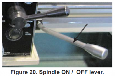
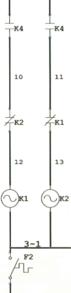
6. The right most section of the drawing is the most important portion: It makes sure that only one or none of the relays, K1 or K2, is engaged at any one time. Also, if the spindle on/off lever is engaged (in forward or in reverse position), and if there is an interruption of the power to the lathe, then power is NOT suddenly applied to the motor at the end of the power interruption. The lever must be returned to its neutral position, then to the forward or reverse position before the power is applied to the motor. This prevents sudden and unexpected behavior of the lathe, especially if the power interruption was for a prolonged time.
View attachment 376550
The foot brake disconnects the 24 volt to the safety circuit. F2, which senses overload of the motor, also can disable the circuit, removing power from relays K1 (motor reverse), K2 (motor forward), and K4 (no power interruption).
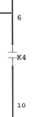
K4 relay does two things: once it is energized, it is self sustaining: it remains energized. This is done via w4, K4, and w5 which routes power to K4 coil (itself). Once K4 is energized and there is uninterrupted power, the circuit containing w6 and w10 and the circuit w7 and w11 can route power to coils for K1 or K2. If there is interruption to power, then these circuits are inoperable.
7. A portion of the above diagram is repeated below: It says, either K1 (motor reverse) or K2 (motor forward), but not both can be energized at the same time. It is also possible that both relays are not energized (no power to the motor). This is a safe behavior, even if LS3 and LS4 misbehave.
8. F1 is not as described in the parts list: It is not a 3P50A, FSX-303, instead, there are three separate fuses as indicated in the drawing.
In the next posting, I will discuss
1. where I intend to insert nonintrusive sensors on my machine so as to preserve the safety functions;
2. how to sense foot brake activation, without changing anything about the peddle nor the associated switch;
3. how I plan to integrate the Hitachi WJ200-075LF VFD.
The goal is to not alter the safety circuit; continue to use the overload fuses; follow Hitachi's direction about direct connect to the motor, except for emergency disconnect; enable the VFD to take in 'forward' or 'reverse' signal, and also the foot brake activation;
Others have integrated VFD with their lathes. I have learned a lot from their postings. I thank them for the postings. I have confirmed what I can from the Hitachi manuals. But my approach to the VFD integration will be piecemeal, a step at a time, so that I will always have a safe, operational lathe that safety functions are comprehensible to me.
Attachments
- Joined
- Sep 8, 2019
- Messages
- 4,392
You will end up with better functionality with a VFD vis a vid variable spindle speed (and more efficient acceleration in the spindle, I think (?)), but it was *very* easy for me to buy an American Rotary AMP-10. That RPC is whisper quiet. When I get my 3 phase mill, all I will have to do is plug it in to the same RPC (which has 3 outlets).
The functionality you get with an RPC is what you would get if you plugged the machine in to a native 220V, 3-phase outlet. In other words, the machine functions as the engineers designed it, to include the limited & discrete RPM choices.
The functionality you get with an RPC is what you would get if you plugged the machine in to a native 220V, 3-phase outlet. In other words, the machine functions as the engineers designed it, to include the limited & discrete RPM choices.
This is a continuation of post #616 and #617.This is a continuation of posting #616.
F2 and F3 are IEC style thermal overload relays. F2 is rated 16A to 24A and F3 is rated 0.25A to 0.4A.
View attachment 376590
3. In the middle of the drawing there is a transformer, T1, which provides 24 volts used for the relay logic, for the work lamp, and the 'power present' indicator lamp. The 24 volt and its 0 volt reference are floating: that is there is no direct tie-in with the power circuit. The body of the transformer is connected to the ground. LS1 must be closed (connected), that is, the end cover must be installed; and the emergency push button switch, SPB1, can interrupt (disconnect) the power to the relay logic, the safety circuit, and shut down the system.
View attachment 376591
4. In the above diagram, W2, SW1, K3 coil, and F3 make up the control for the coolant motor. Closing (connecting) SW1 energizes relay K3, which then routes power on R and S to U1 and V1.
5. Between w2 and w6 there is push button switch PB1, which is the JOG switch. But on the face plate of the lathe, it says not to use the JOG, but rather hand manipulate the chuck when shifting gears. So, it's probably best if that circuit was disabled on my machine.
View attachment 376592
6. The right most section of the drawing is the most important portion: It makes sure that only one or none of the relays, K1 or K2, is engaged at any one time. Also, if the spindle on/off lever is engaged (in forward or in reverse position), and if there is an interruption of the power to the lathe, then power is NOT suddenly applied to the motor at the end of the power interruption. The lever must be returned to its neutral position, then to the forward or reverse position before the power is applied to the motor. This prevents sudden and unexpected behavior of the lathe, especially if the power interruption was for a prolonged time.
View attachment 376550
The foot brake disconnects the 24 volt to the safety circuit. F2, which senses overload of the motor, also can disable the circuit, removing power from relays K1 (motor reverse), K2 (motor forward), and K4 (no power interruption).
K4 relay does two things: once it is energized, it is self sustaining: it remains energized. This is done via w4, K4, and w5 which routes power to K4 coil (itself). Once K4 is energized and there is uninterrupted power, the circuit containing w6 and w10 and the circuit w7 and w11 can route power to coils for K1 or K2. If there is interruption to power, then these circuits are inoperable.
View attachment 376593
7. A portion of the above diagram is repeated below: It says, either K1 (motor reverse) or K2 (motor forward), but not both can be energized at the same time. It is also possible that both relays are not energized (no power to the motor). This is a safe behavior, even if LS3 and LS4 misbehave.
View attachment 376598
8. F1 is not as described in the parts list: It is not a 3P50A, FSX-303, instead, there are three separate fuses as indicated in the drawing.
In the next posting, I will discuss
1. where I intend to insert nonintrusive sensors on my machine so as to preserve the safety functions;
2. how to sense foot brake activation, without changing anything about the peddle nor the associated switch;
3. how I plan to integrate the Hitachi WJ200-075LF VFD.
The goal is to not alter the safety circuit; continue to use the overload fuses; follow Hitachi's direction about direct connect to the motor, except for emergency disconnect; enable the VFD to take in 'forward' or 'reverse' signal, and also the foot brake activation;
Others have integrated VFD with their lathes. I have learned a lot from their postings. I thank them for the postings. I have confirmed what I can from the Hitachi manuals. But my approach to the VFD integration will be piecemeal, a step at a time, so that I will always have a safe, operational lathe that safety functions are comprehensible to me.
F1 in the chassis diagram is misleading: there are actually three separate fuses at the F1 location. They are each Keyon 14x51 mm, 40A, 600V fuses.
I agree. Especially with respect to safety circuits. I have a phase converter, from single to 3 phase. It's giant, and did not make it in a temporary move across town.You will end up with better functionality with a VFD vis a vid variable spindle speed (and more efficient acceleration in the spindle, I think (?)), but it was *very* easy for me to buy an American Rotary AMP-10. That RPC is whisper quiet. When I get my 3 phase mill, all I will have to do is plug it in to the same RPC (which has 3 outlets).
The functionality you get with an RPC is what you would get if you plugged the machine in to a native 220V, 3-phase outlet. In other words, the machine functions as the engineers designed it, to include the limited & discrete RPM choices.
I am going to do the minimal, safe addition of the VFD to my lathe. That's why I had to understand the circuits as they are in the machine at this time.