- Joined
- Nov 20, 2018
- Messages
- 710
Thanks again. I may do the same. I had considered cutting a tapered hole and boring the hex shaft large and deep enough to slip a nut on the shaft to pull it into the taper much as the original wiper arm was done. Your way seems easier and if the torque load is low enough the pinning should be enough in addition to the taper.
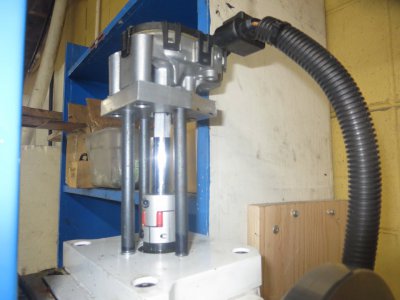
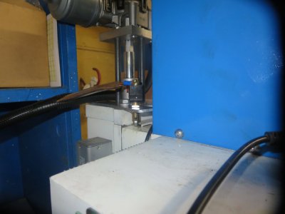
I just need to accumulate a couple more pieces and I can begin the build. I had thought hooking up to the mill itself was going to be the hard part but I think I have that all figured out. I have a lovejoy coupling coming with a 14mm bore and a slit side to tighten it up on the shaft. I intend to remove the top locknut off the mill and thread the lovejoy fitting to match and then cinching the slit tight to hold it.
I just need to accumulate a couple more pieces and I can begin the build. I had thought hooking up to the mill itself was going to be the hard part but I think I have that all figured out. I have a lovejoy coupling coming with a 14mm bore and a slit side to tighten it up on the shaft. I intend to remove the top locknut off the mill and thread the lovejoy fitting to match and then cinching the slit tight to hold it.
") ), so it wouldn't have been a big deal to remake the entire setup if the motor failed.
), so it wouldn't have been a big deal to remake the entire setup if the motor failed.