- Joined
- Feb 25, 2019
- Messages
- 24
Awesome, thanks a bunch Dave. Going to dig through them now

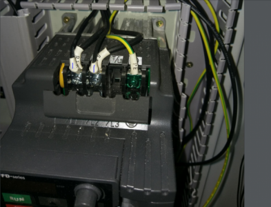
Our wiring is different and looks like I do not have the two other wires exiting from the top of my VFD as marked with the blue streaks.
I'm going to look at your wiring diagram and compare it to mine. This is odd.
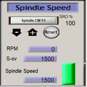
Our spindle works, but the RPM setting is nowhere near what I physically measure with my naked eye (and a paint mark). In addition, we are still getting a reading of zero RPM in both screenshots even though the spindle is operating and spins higher/slower according to my setting.
Hi Sal,
I woke up this morning thinking about your situation with the spindle speed. I guess I may not fully understand all of your description of the spindle speed issue.
You said: "Our spindle works, but the RPM setting is nowhere near what I physically measure with my naked eye (and a paint mark). In addition, we are still getting a reading of zero RPM in both screenshots even though the spindle is operating and spins higher/slower according to my setting."
Fixing the pulleys configuration setting to 1000 rather than 1500 should have help to remove some confusion, but should not change the maximum speed of the spindle. Then setting the Mach3 Spindle Speed RPM to 1000 simply means that the actual spindle RPM is 100% of the VFD max setting. Likewise, Mach3 Spindle Speed RPM at 500 would mean the spindle RPM is 50% of the VFD max setting. Phazor2 maybe correct that the VFD internally maybe off, but I would not mess with it until you have exhausted the other possibilities. (I have not read about how to adjust this yet.) (By the way, if there truly is something wrong with your VFD component I think that PM warranties the parts for 3 years.?)
Also, from your comment above and the screenshots we learned that. 1) zero RPM is always the case in Mach3 as there is no tachometer feedback and so there is nothing to be displayed in this box 2) "Spins higher/slower according to my settings" I assumed this means that you are typing in a number in to the small button box "Spindle Speed" of the Spindle Speed window and hitting enter to make it change. At which point the spindle responds to the new speed. If this is the case, then it seems to me a digital code is being sent to the nMotion and then a DC signal must being generated by the nMotion and sent to the VFD pins via the input wires 079 (ACM) and 081 (AVI). Hence, that is working. So that leaves: 3) "RPM setting is nowhere near what I physically measure" This has no quantitative info except that you say that "the spindle spins higher/slower ....... as it should." This makes me think that all is working but that you just have no real way to measure the physical speed.
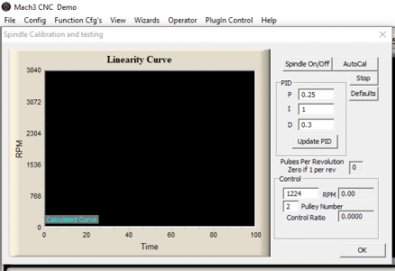
Short of you buying/borrowing a simple strobe type tachometer there is not a lot you can do to ensure that the speed is calibrated/functioning properly.
I used the following g-code to watch my spindle speed increment up from min to max." Maybe you want to try it?
(In Mach3, the General Logic configuration check the box for G04 setting to Dwell in millisec.)
(Spindle to turns on at 60 rpm, then wait 10 seconds, then increase the spindle to 200, wait 10 sec., etc.)
M3 (spindle on)
S 60 (spindle speed 60 rpm, one revol per second)
G4 P10000 (dwell 10000 milli seconds, 10 seconds)
S 100 (spindle speed 100 rpm)
G4 P10000 (dwell 10000 milli seconds, 10 seconds)
S 200 (spindle speed 200 rpm)
G4 P10000
S 300
G4 P10000
S 400
G4 P10000
S 500
G4 P10000
S 600
G4 P10000
S 700
G4 P10000
S 800
G4 P10000
S 900
G4 P10000
S 1000
G4 P10000
S 0
M5
This turns on the spindle, sets the speed to 60 rpm, then dwells at his speed for 10,000 milli seconds, then increments the speed up, dwells, etc etc etc. If this code will not run for you then you might have to change the G4 setting in the General Configuration check boxes. G4 P10000 is suppose to mean "Dwell for 10,000 milliseconds" where the P means milliseconds and is suppose to be independent of the machine configuration, but I found that I needed to check the configuration box for G4 indicating milliseconds. I think this maybe because the G4 command is non-modal and is usually combined in the same line with another G code.
I ran this program and recorded the spindle motion for you. Maybe this will give you a better feel for speeds.
Dave