
Ignorance on my endWhy did you have to get a new VFD?

-
Welcome back Guest! Did you know you can mentor other members here at H-M? If not, please check out our Relaunch of Hobby Machinist Mentoring Program!
You are using an out of date browser. It may not display this or other websites correctly.
You should upgrade or use an alternative browser.
You should upgrade or use an alternative browser.
PM-940V
- Thread starter SlowJoe93
- Start date
Hi,
I have an PM940M_CNC_VS , which I purchased in late 2017. I don't think PM sold many of these as the CNC version never seems to be on the web site. Mine has a Delta VFD, MODEL: VFD015E21A in it and a 1.5KW 3phase motor. I have never connected a PC to it, but it seems to be a pretty simple set up. Digital inputs for Start/Stop, CW/CCW rotation and an analog 0-10Vdc for speed control. You can look up the model manual on the web ( just googled the model number with the word manual and got serveral hits. ) and probably figure out how to program it even via key input .... even without a PC connection. But, what information would you want from my set up? I have not tried, but can probably pull up individual settings via code number. URLs for the Manual, for example: https://www.galco.com/techdoc/dlpc/vfd055e23a_um.pdf See page 32 of 399. Or at https://www.manualslib.com/products/Delta-Electronics-Vfd015e21a-7135376.html
Dave
Thanks Dave but PM got back to me with the correct settings. I'm going to plug in the settings and if they work I'll post them for future people like me. I appreciate the helpHi,
I have an PM940M_CNC_VS , which I purchased in late 2017. I don't think PM sold many of these as the CNC version never seems to be on the web site. Mine has a Delta VFD, MODEL: VFD015E21A in it and a 1.5KW 3phase motor. I have never connected a PC to it, but it seems to be a pretty simple set up. Digital inputs for Start/Stop, CW/CCW rotation and an analog 0-10Vdc for speed control. You can look up the model manual on the web ( just googled the model number with the word manual and got serveral hits. ) and probably figure out how to program it even via key input .... even without a PC connection. But, what information would you want from my set up? I have not tried, but can probably pull up individual settings via code number. URLs for the Manual, for example: https://www.galco.com/techdoc/dlpc/vfd055e23a_um.pdf See page 32 of 399. Or at https://www.manualslib.com/products/Delta-Electronics-Vfd015e21a-7135376.html
Dave
Hi Joe,
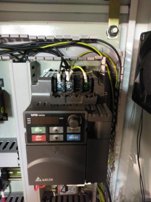
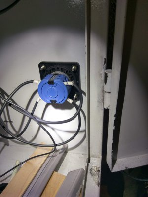
So all of this stuff about wire gauge is a bit confusing, but let me try to set your mind to rest a bit. As, I said before, I have a little different machine than yours, but the basics are the same. The cabinet for my CNC version does not look anything like yours so I will not post it here, but there are other pictures already posted by others. What I am posting for you are a couple of pictures of my VFD wire wiring and the cabinet power switch. By the way, my motor is 1.5Kw which is more like a 2HP not 3HP.
I think you are trying to follow codes on wires and that is good. (But not all wires of the same gauge can carry the same current. (But a bit more about this on down.) Also, the current per wire of the three current carrying wires for three phase can be different than the current per wire of the two current carrying wires, in single phase. So think of it this way , the "load" on a 220 single phase circuit is essentially the same as the load on the three phase circuit, i.e. it is the same motor. There is some inefficiency in the VFD so it takes a little power also, but not a lot. They are pretty good at doing the conversion. So lets assume the load, Watts, are the same, power as it would be with or without a VFD. Power is defined as P=IV= single phase power = three phase power, where the single phase power is being carried to the load with 2 wires and the three phase power is being carried by 3 wires. So the current value in the three wires is a smaller value per wire, than current carried in each of the two wires of the single phase wires. So naturally the gauge of the wires could be different. The 3phase wires coming out of the VFD to the motor could be smaller than the single phase wires going into the VFD.
But there is yet another twist. Not all wires of the same gauge are equal in their current carrying capacity, because not all wire insulation are equal. If you look at a the wire insulation you can usually find some letters on it, indicating its ratings. Normally we wire our house with romex NM wire. The NM indicates the code you are thinking of. i.e. Single phase, two wires, 220V 30A wire is 10 gauge. (20A is 12 gauge, 15 A is 14 gauge, etc.) There are lots of other insulation ratings for higher voltage( electrical break down) and for higher operating temperatures (decomposition or melting). Meaning that 30A can go out one wire to the load and return in the other wire. It does so over reasonable distances without a substantial voltage drop along the wire. The voltage drop along the wire tells us that some Watts are being dissipated along the resistance of the wire heating it up. (Ohm's law V=IR or for power, P=IV=I^2R= V^2/R) . Since the wire has length this is dissipation per length. The longer the wire the more power is lost. So the logic is that there should not be too much loss in the wires or there will be no power left for the load! Likewise, the heat per unit length should not get the insulation so hot that it would fail.
Inside the cabinet, the wire size and insulation are most likely different from that which is bringing the power to the cabinet. It also matters that the wires in Romex are next to each other and encased in the outer insulation where as the wires inside the cabinet are separate most of the time. Meaning that their heat can escape to the air easier. Anyway, It is common that inside the equipment one changes the wire gauge and insulation ratings so that smaller gauge (diameter) wire can be used to bend and to make connections. For, example, if you open up an electric oven you will find that the wires going to the oven maybe 220V 2phase at 20Amp, but once inside the connection box the gauge maybe 16 or even smaller diameter, but will have a higher temperature rating. This wire is inside the oven or metal conduit so its elevated temperature does not touch much of anything.
By the way , it was mentioned the current draw can be different when the motor is starting, and definitely is higher if the motor is stalled. This is because the impedance (dynamic resistance) of motor changes. (related to the term "back EMF"). Circuit breakers are designed for a certain amount of this as they allow short transient time periods of extra current before they get hot enough to trip (think slow blow fuse). Likewise, wires can over heat for short periods before it becomes a problem.
Lastly, there is never anything wrong with having too large a wire carrying capacity .... if it makes you feel better... it just cost more $$. You just never want to put in a breaker that is rated larger than the current carrying capacity of the wires that you use ... as described above, capacity is not determined by gauge alone!
Dave
Attachments

Thanks for the photos Dave. I really appreciate the help. I should have been a little but more clear in my last reply. I got my machine up and running however I can't get it go to more then 2000 rpms. I checked that it's getting full power to all the lugs. The vfd is oscillating power to all three phases which I'm guessing is normal. I plugged in the numbers which are as follows from PM
01.01 60Thanks for the photos Dave. I really appreciate the help. I should have been a little but more clear in my last reply. I got my machine up and running however I can't get it go to more then 2000 rpms. I checked that it's getting full power to all the lugs. The vfd is oscillating power to all three phases which I'm guessing is normal. I plugged in the numbers which are as follows from PM
01.02 220
01.09 02
01.10 03
01.26 60
01.27 220
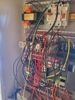
Reason why I asked for the picks was I was seeing online the photos of inside the box looked a little different then mine. Sorry for the wiring mess I was making sure everything was working
Attachments
Hi Joe,
You are correct, I totally missed what you were trying to figure out when you ask for the pictures. I do not have a VS machine and so I do not know what the pulley ratios are nor do I know about your motor speed for 60Hz input. So I could not tell you what the final RPM is at the spindle for a given frequency from the VFD. ptrotter may know those things since he has that machine.
However, a couple of things. I think your machine has a tachometer display that you are reading for the rpm. According to PM the maximum speed you should be able to get is 5000 rpm. On the side of the motor it should say what the RPM of the motor would be if the motor was getting 60Hz input. Typically these motors are rated at 1800 rpm or less. It might be as low as 1200rpm??? So taking 5000/1800=2.8, so this would mean that the frequency the VFD would have to be outputting would be 2.8*60Hz=167Hz. If the motor out put was 1200 rpm for 60Hz, then the number would be 4.17*60Hz=250 Hz.
Now lets look at the settings you say that PM just sent you. Look at the VFD manual, which you can down load at PM or you can get it at the URL I sent you earlier. The programing parameters appear to start on pdf page 57. There you will see the parameter meanings
The first parameter setting you listed was
01.01 60 This is the first one on the list and is the maximum frequency, 60, the VFD is going to run for a voltage input. So with 60Hz and an 1800rpm motor(?) the spindle would be turning at 5000/2.8 = 1785rpm. According to this parameter table, the VFD is capable of sending out a frequency from 0.1 ti 600Hz, but with this setting, 01.01 60 it is only going to put out a maximum of 60 Hz as you vary the input speed voltage to 10Vdc.
The first guess then is that the maximum should be set at a higher value than 60Hz.
You can look at the other parameters and see if they make sense.
Dave
- Joined
- Mar 16, 2017
- Messages
- 145
The belt drive is not one to one so it shouldn’t need 250hz to get 5000 rpm. I have the same mill although I changed all the electronics, I did look at the original VFD programming and I think I remember maximum frequency to be around 150hz. You do have it in the high speed pulley position, correct?
The belt drive is not one to one so it shouldn’t need 250hz to get 5000 rpm. I have the same mill although I changed all the electronics, I did look at the original VFD programming and I think I remember maximum frequency to be around 150hz. You do have it in the high speed pulley position, correct?
I read and read the book that came with the new vfd and decided to change the
01.01 200
01.26 200
Since the 3 phase motor said it was capable
And neither helped. Doing some more reading they never said anything about changing the first parameter
01.00 maximum output frequency 50-599 htz I placed that at 150 and the machine got up to 4980 rpms. So that will be fine. I think I changed another setting because now the small nob on the vfd is making the speed changes instead of the nob out front which should be. The setting for this is
02.00 1 instead of 2. I ran out of time to change this.
I appreciate all of your help. I'm going to email PM tomorrow.