Pm1340gt Lathe Basic Vfd Control Conversion Using The Stock Control Board And Switches

@Provincial

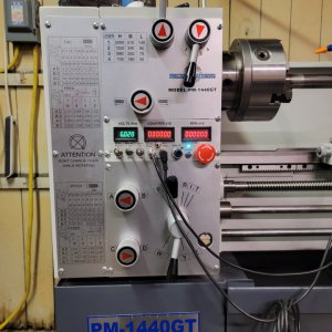
I wanted 16 wires in a shielded cable for my 1440GT conversion. But could not find it in a package that would fit through the hole in the side of my lathe. I settled on two cables with, 20AWG stranded, 8+ground+shields and they slipped in nicely. I agree with Mark, the 24 gauge is to fragile. Even if it does not break it does not work all that well at the end connections. I provided a link to the cables I purchased in the parts list of my conversion post. See the Part 2 document. These cables are made for the marine environment so should hold up well. I spend quite a bit of time analyzing them and their metallic structures before I installed them. I use elevator style screw connectors and they clamp well. Since the individual wire have colors I also stripped the outer cover off so I would have colored wires to use. I found that I could also Ferrule crimp them nicely to go into either the elevator connectors or the VFD inputs.
VFD conversion using solid state electronic components.
I think this may have been the product, but I know that I purchase a 50' roll which they no longer seem to offer.


" 20/8 AWG Round Signal Tinned Copper Marine Wire - Grade 8 Conductor Shielded Signal Cable - White Jacket, Black/Red/Green/Blue/Brown/Orange/Purple/Yellow - Made in USA "
 
After I bought the 8-conductor cable, I found the 12-conducter cable I posted in #121. I have since run a piece of 1/2" Non-metallic Liquid-tight flex conduit to a box mounted to the change gear cover and used one length of 4-conductor for the speed pot and one piece of 12-conductor for the other control wires and 12V + and- for the tachometer. It all fit well in the conduit (I can remove and replace either cable while leaving the other in place) and I like the 18 gauge wire. This leaves me with one unused wire in each cable. I haven't hooked up the wires in the control box yet, as I haven't worked out how to make it fairly easy to service the internals of the control box, or design a mount and install the tachometer sensor. I am also researching getting labels made for the switches on the control box.

I am moving ahead in fits and starts as I have lots of other things on my plate right now. I did get all the switches and tachometer readout mounted in the control box, drilled the lathe stand for mounting the VFD enclosure and test mounted it, and mounted all the items on the back plate for the enclosure. I also got the braking resistor mounted in the enclosure and drilled the hole for running the carriage forward/reverse wiring into the enclosure. I got the master switch mounted in the enclosure and wired up everything except the SOOW cables in and out. I'll wait on those until I'm ready do the final mounting of the enclosure onto the lathe stand. That will be easy, since I am running them through a factory-provided removable plate that mounts on the bottom of the enclosure. At that time, I'll also permanently mount the control box to the gear cover and support the conduit with a cushioned clamp.

I'm beginning to believe that I can actually complete this project!

As an aside, has anyone used the Analog Output from the Hitachi using the AM and L terminals (C028, code 20, Inverter Output Frequency) or Function C028, code 03, Digital Output Frequency) to monitor frequency to the motor with a remote display? I know I can display this on the VFD itself, but it will live behind a closed door and is pointed toward the left end of the machine. I could remote mount the front panel, but it seems like that would expose it to the elements.
 
Last edited:
I'm setting mine up with 5 different cables, mainly because that's what I already had. I'm using an 8-conductor 22AWG for the controls, 3-conductor 16AWG shielded for the speed pot, 4-conductor 14AWG shielded for the motor, 8-conductor 16AWG for the 12v and 24vdc power and a 2 conductor to a coolant solenoid. I plan on just tie wrapping the speed pot and control cable together, and the motor and DC power cables together and keeping them separated as much as possible between the VFD cabinet and the lathe. The cable for the coolant will run to the other end of the lathe, so it will be a separate run.

I have the VFD cabinet complete and mounted on the wall, now all I need is the lathe.
 
Sorry, about the 8 wire cable post. My conversion was for a 1440GT and you have a 1340. I think the opening into the front panel on your machine is a lot larger than on the 1440. Basically, in the 1440 there is a hole through the cast material (~3/8" thick) into the control electronics enclosure. With out opening it up a larger cable would not really fit. I got two of my 8-wire and a small cable from the spindle Hall effect sensor through that hole just fine, but the original lathe cable with its thick OD insulation left little to no room for any thing else. From the images I have seen of the 1340 opening it appears to be more of a slot between to pieces of metal so would be larger? Anyway, my wires work fine for me. I needed all 16 wires for my set up.

Now with respect to your question:

As an aside, has anyone used the Analog Output from the Hitachi using the AM and L terminals (C028, code 20, Inverter Output Frequency) or Function C028, code 03, Digital Output Frequency) to monitor frequency to the motor with a remote display

I looked into this and even provided one of the 16 wires up to the front panel to measure the VFD output frequency determined via analog output voltage. Then I ask why do I need to see this frequency when I am already monitoring the RPM via the spindle its self. The real thing I wanted to know was what frequency, approximately, the VFD was going to be running out BEFORE I turned it on so that I could preset the value .... not after I turned it on. Naturally, the voltage or frequency value coming from the VFD only shows up after the VFD is running the motor so this is of little value unless you are varying the speed during operation, like in a paper mill, and want it for feed back control. So I just installed a volt meter in the front panel and connected it to the pot output. This voltage then tells me where the pot is set before I turn on the lathe. The voltage in either case is from 0-10 volts and so is only proportional to the VFD frequency not a number that equals the frequency. I also measured the voltage from the pot to the VFD to determine the frequency vs pot output. I found that the frequency was not exactly linear with the pot wiper voltage, but was close enough to give me an idea of what the resulting voltage would be. This is probably due to the VFD loading down the pot a bit as the input to the VFD is not high impedance. I then set the max frequency on the VFD to about 108 Hz. This then resulted in the voltage at the wiper pot, and so my volt meter, to be 6 volts when the frequency out of the VFD was 60 Hz. The linearity is not so bad that the volt meter reading is very far off at the lower frequencies or higher frequencies... and I seldom run the lathe anywhere near 108 Hz any way. By using a max frequency near 100 Hz the volt meter measurement in Volts is equal to the Frequency/10. So I do not have to do much of a mental conversion!

Some may express concern that the panel meters generate noise and hooking one of them up to the pot output, going directly to the VFD, might create a problem for the VFD. At least in my design I have not found this to be a problem at all. If you did then just hang a capacitor on the line to kill and noise the spikes.

Lastly, I gave a link to my conversion earlier at posting #121. At that link there are photos and documents about my conversion and the Part 2 appendix provides a list of components use in the conversion. There in those photos of the front panel, and below, you will see the three meters that I put into it along with all of the other devices. I monitor, the Spindle RPM, the VFD input voltage, and I have a spindle Revolution Counter. The counter also has an additional feature so there is a mini switch to select that mode. I posted the Excel program I used to generate the G-code to make the holes in the panel. It is linked at the conversion site. I found it especially handy when I remade the panel meter and needed to add devices and move the previous ones around. I found these RPM and counter displays, which are smaller than most, to be quite visible and readable. They work nice and cost about $14 each.... from China though so take 4 weeks to get. The design and layout is nice an neat with no EXTERNAL meters! If interested, you may want to check the operating voltages as not all meters will work on 24Vdc. I did drop the 24Vdc down to 12 via a simple 3 terminal regulator at one point. I think it may have been for one of the meters and then used on all three. A lot of these devices are made to be used in automobiles which do not usually run at 24 volts.

By the way, I think the front panel for the 1340 is almost exactly the same size as that of the 1440. It is the same width, but the 1340 may be slightly taller. I do not know the dimensions of the inside of the 1340 front panel enclosure. I think the devices that I use would also work with your conversion.

Dave L.
 

Attachments

  • 20211222_001306.jpg
    20211222_001306.jpg
    101.2 KB · Views: 117
  • PM1440GT Instr Panel LC26.jpg
    PM1440GT Instr Panel LC26.jpg
    195.4 KB · Views: 106
  • 16DeviceHoles LC27 - Copy.JPG
    16DeviceHoles LC27 - Copy.JPG
    32.3 KB · Views: 98
  • 20211220_184608.jpg
    20211220_184608.jpg
    104.1 KB · Views: 89
@Just for fun if you're interested, here are the dimensions for the control switch panel on my 1340GT. Others report the positions of the screw holes that mount that panel vary from machine to machine - I assume they are individually hand drilled/tapped at the factory. I had FrontPanelExpress make replacement panels and if you want those design files, let me know - happy to share.

screenshot_5443.jpg


IMG_4798.jpeg
 
Hi @davidpbest

I am curious, do you have info, pictures and dimensions you could share on the hole (enclosure) that is behind the panel? Depth, width, ... where the wires come in, etc.

Dave L.
 
Thanks David, I think the 1236T has different size opening. I may still take you up on the files for the panel.
 
Hi @davidpbest

I am curious, do you have info, pictures and dimensions you could share on the hole (enclosure) that is behind the panel? Depth, width, ... where the wires come in, etc.

Dave L.
I have some photos and another drawing that might help. As part of my 1340 build, I completely stripped the machine back to bare metal, did a proper Bondo job to the castings, and repainted it. So I have photos of all that that will give some idea what the head casting looks like stripped down. I also implemented a one-shot oiler system that dealt with the mickey-mouse oil squirt-ports on the sides of the headstock, and that aspect caused me to make a new bottom plate that distributes the oil to the Norton gearbox and is also the bottom mount for the switch panel.

Shown below at the red arrows is how the cable system comes into the machine for the front panel switches - through a gap. The green arrows point to an aluminum casting who's primary purpose is to provide an attachment point for the front panel to screw into along the bottom.

screenshot_5445.jpg


This photo will give you some idea what the cavity looks like behind the switch panel - that bottom support casting for the front panel is not shown in this photo - it just rests in place.

screenshot_5446.jpg


This photo shows the oil distribution plate I made to replace the factory unit. That process if fully documented here.

screenshot_5448.jpg


This is how it all worked out with the new plate installed, the new switch panels, and how I provisioned for the wiring and oil connection. Note that the switches are also at an angle, and I had to dish out the replacement plate to give clearance to the mechanical aspects of the switches behind the panel.

screenshot_5447.jpg


This is the drawing for the oil distribution plate. From this you can get approximate dimensions front to back for the cavity. The casting walls on either side of the cavity are about 1/2" thick, but they taper as you can see in the first few photos, and the front is sloped at an angle. A clearer drawing is attached.

51193768426_d99f7c7529_k.jpg

Hope this helps.
 

Attachments

  • PM1340 Lathe - Bijur Oil Pump Distribution Plate.pdf
    210.4 KB · Views: 101
  • Like
Reactions: B2
The 1236T has a shorter front panel, PM me if you want a file for the front panel, these days they run about $100 for the new switch panel.
 
Back
Top