Pm1340gt Lathe Basic Vfd Control Conversion Using The Stock Control Board And Switches

I have no idea what design you are using, the basic install uses the contactors and the stock AC transformer. You cannot mix power for the relay controls with the VFD inputs on the relay designs I have done, not sure why you would want to do that since the VFD has its own internal power supply. I have done designs for other VFD's that use a single supply, but there are issues of electrical noise and voltage spikes from the relays that could damage the VFD inputs. I did one build that way and designed subsequent systems keeping everything separate. A 10W 24VDC power supply is pretty marginal, depends on the design but I usually use 65-100W. The system current draw with small relays and if I using a coolant contactor is around 500 mA 24VDC. On smaller builds I will use a step down converter to get 12VDC, otherwise I use two separate power supplies.

E-Stop is different then turning off the power, in one case you want to kill the run commands to the VFD and issue a fast stop, depends on the VFD and the control design. In some cases people choose to have it shut down the output section of the VFD (safe torque off), etc..
 
Mike, I'm not using any of the contactors. I'm running my motor entirely off the VFD, and controlling power to the VFD with a manual switch. My loads on the 24V system are the same ones your basic design powered with the VFD 24V output, with the exception of the tachometer, which is a pretty low draw. The only relay in my installation is the 784-4C you call out. I don't have a coolant pump or lights, and any I add will be stand-alone 120V.

From what I have read on the web, I will be far ahead by not using any of the original contactors and electrical parts. I am going to use the stock forward/reverse switch that is controlled by the lever on the carriage. Other than that, everything is different. The original system was single phase, and was prone to burning up motors because of a bad design.

I could easily use the converter to power just the tachometer, and everything else with the VFD using your design. I just thought that having the converter would eliminate the risk of overloading the VFD 24V circuit, which has very little capacity.
 
The needs of the many outweigh the needs of the few.
 
I would use the VFD internal power supply, you are not going to overload it, that was the whole basis for the single relay design. It is simple and did not need an external supply. I have dozens of system designs, year past the single relay design was easy for others could follow, the current basic design is for use of the stock contactors to activate the VFD inputs and using the stock 24VAC transformer for lights, tach (24VAC to 12VDC converter), etc. Many people do not want to deal with tearing out and replacing everything. But if you have no control system, the single relay design used with the WJ200 is a good, simple alternative. Hopefully you have the 4 pole relay, Automation Direct has been out of relays and sockets for months.
Mark
 
Yes, I was able to find the proper relay, socket, and diodes on the Bay. Based on your reply, I think I will just use the 24V power supply to run the tach system and use the VFD for the controls. That will make the tach stand-alone and less likely to affect the control circuits. I'll probably run two 8-conductor cables to my switch box, since I'll need 14 wires (3 for the Pot, 9 for the switches, and 2 for the tach) because I'm putting the jog forward/reverse switch there. I can check around for some 12-conductor cable if it is critical to separate the speed control wiring from the others to minimize RFI. In that case I would use a 4-conductor for the speed control and the 12-conductor for everything else.

It is a relief that we are now on the same "frequency." I was afraid that I had overlooked something in the wiring diagram and was running off the rails.

Edit to add: I apologize for calling you Mike. I don't know how I mixed that up! I'll claim old age.
 
Last edited:
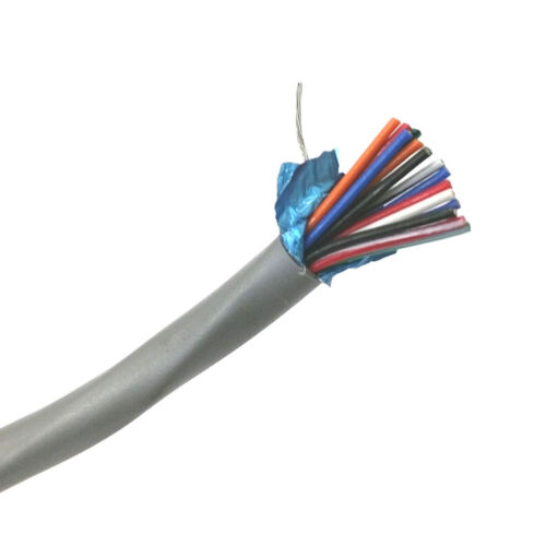
Not aware of 14C shielded cable, typically would be 15C or 16C. and pricing can go up quickly. Not that it is needed but the most cost effective would be a 12C and a 3C shielded in 18AWG. There is an eBay listing for a 15C in 24G, which would work but I find the small gauge wire to be a bit fragile. You also would want to use stranded wire as opposed to solid as it will be less likely to fatigue/break over time if there is movement. You will need to use crimping pins for the VFD end. Also be mindful that the VFD connections are correct and the jumper is moved.

25' Quabbin 8205 15 Conductor 24 Gauge Shielded Cable 25 Foot Length ~ 15C 24AWG
 
I did find an Ebay listing for 18/12 cable. More than I need now, but if I do a VFD conversion on the Atlas, it wouldn't be that much excess. Good brand name, and I think the PVC jacket should hold up pretty well. About $2.00/ft.

Carol E2041S Riser Cable 18/12
 
Back
Top