PM1440-2SM VFD conversion

I removed belt guard and chuck cover interlocks, it was just an annoyance to me, but don't tell anyone. ☺
In my experience, if I use foot brake I want chuck to stop. Why would I want to use foot brake to just kill electric and release?
KA 21 and 22 are part of the VFD P24 circuit, it is a separate contact from the rest of the AC circuitry.
Noted on the USP, will correct.
Thanks Mike
 
I figured you removed the other safety interlocks. In some cases if something lets go, you try to engage the foot brake and then step back to save your skin. I have a foot brake on my lathe, about the only time I use it is when the chuck is stopped and I need to hand tap, but still have it rigged as described. If for some reason I do not complete braking to a stop it goes into a fast stop (1 second) condition. Just a matter of safety what if...
 
Mike,
That is why I used the EXT input to disable the ENTIRE system when the foot brake is applied and this results in a Free Run mode so that the e-brake and the foot brake are not in conflict. I consider hitting the foot brake, while the lathe is running, to be a REAL emergency... like that when someone is in danger of being dragged into the lathe! Why would anyone want to hit the foot brake to stop the spindle and then have it fire right back up when the foot brake is released? (I have had bad automobile cruise control systems do this and it scares the dickens our of me.) The foot brake situation is different from using the E-stop, which you might hit just to stop a feed, or some other motion, from crashing the tool into the spindle or into the work ... a mistake not a REAL emergency. So the E-stop like other limit switches just disables the run latch in my circuit. If you want to lock the spindle with the foot brake to do some form of hand work it is probably just fine that the lathe is shut down.

Anyway, there is lots of flexibility in the VFD programing and connections as to how one wants to implement these various features.

By the way, there are 7 intelligent inputs not 6 as you have in your drawing!? Below is the figure from the manual and below that is the figure generated for the documentation about how I set my lathe up. For this figure, see, Part 2, Figure 4, pdf page 37 of 44. https://www.hobby-machinist.com/att...-vfddescript-links-dnl-l910_1440b-pdf.378083/ You can see the sequence of the various switches in my circuit at Part 2, Figure 3, pdf page 36. You will see that 24Vdc goes to the foot brake switch which is normally closed. On the down side of this switch the line goes to EXT and to other circuits. So if the foot brake is used the 24Vdc is interrupted starving the EXT input of current (low signal) and so the EXT is activated to shut things down. Mention this only because it is different from the sequence of things you have in your circuits.

I am with Mark, I seldom ever hit the foot brake! But, it is mechanically good, it really does stop the spindle quickly.

Dave


1712086726037.png


1712086857182.png
 
Mark, Dave, just to clarify - if I step on the foot brake VFD will free run and continue to free run even if I released the brake before motor stopped. Motor will not power back up until I reset the control lever to stop and back to F or R.
Now I have very limited experience with lathe. I had 7x12 for 20 years, but that is very different machine. I spent little time with this new 1440. Not sure if it was a correct procedure, I used foot brake to thread to a shoulder. It worked very good. I don't see it as an emergency device, maybe I'm wrong.
Dave, use of the EXT requires subsequent reset. I don't have any space left on the front panel for additional button. I may put reset in the box next to the VFD in the future if needed.
My progress so far - finished all wiring except connecting to the motor. It suppose to arrive in a couple of days. Still need to do some wire organizing and dressing, and program VFD. I replaced all 240VAC wiring to AWG12 - power cable to the outlet, internal wiring to power switch, circuit breaker, EMI filter and to VFD. Left other wiring as is (AWG15 from OEM). The breaker currently 25Amp, maybe need to replace to 30Amp, we will see. And I removed all 240V wiring related to existing single phase motor.
 

Attachments

  • 20240401_131436.jpg
    20240401_131436.jpg
    365.4 KB · Views: 25
  • 20240401_133931.jpg
    20240401_133931.jpg
    352.8 KB · Views: 20
  • 20240402_193837.jpg
    20240402_193837.jpg
    438.7 KB · Views: 22
  • 20240402_193855.jpg
    20240402_193855.jpg
    378.5 KB · Views: 21
  • 20240402_193904.jpg
    20240402_193904.jpg
    353.3 KB · Views: 19
  • 20240402_193911.jpg
    20240402_193911.jpg
    348.9 KB · Views: 20
  • 20240402_205546.jpg
    20240402_205546.jpg
    345.4 KB · Views: 22
Threading with a VFD, you use electronic VFD braking, it is far more predictable and repeatable. You do not want to have to reset the VFD every time you use the foot brake, the usual reset pattern is when the spindle switch goes to the stop position it resets the latching power relay. The only time a VFD would need to have a reset button would be if you have a VFD error, usually because you have incorrect programming, there is an over voltage on the buss or a component failure (it assumes the VFD is sized correctly for the motor). Just keep it simple. Since it sounds like you are new to VFD's there is a bit of a learning curve, and you can always make further modifications at a later point. A 25A breaker should be OK even though the manual specifies 30A. The breaker protects the wiring not the device.
 
Hi Mike,
I too thought that I had to have a reset switch after activating the EXT. However, I now know that not quite the whole story. I think the EXT functions as you mentioned, but this is meant to be the case when there are multiple motors/VFDs and when it it being operated via a computer or some central controller. When the EXT is activated it shuts down the entire VFD and so the lathe. If you then hit the reset you can start the lathe back up, but only after you put the Forward, Reverse, Neutral switch to the Neutral position and activate the latch and VFD. However, if you do not try to use a reset signal, but instead turn the power off to the VFD and wait about 20 seconds (for all of the charge on the VFD internal capacitors to bleed off) to power it back up, then it works again as though it was a cold start: Put the lever into neutral then Forward or Reverse starts the motor. You can try this out if you like. So a Reset switch is not absolutely required. It is just a bit simpler and quicker. So I sort of think of the EXT followed by a Reset signal as being similar to the old PCs. The Reset is sort of like a Control-Alternate-Delete key causing the PC to do a "soft" reboot. However, you can also do a "hard" reboot by power cycling the PC. There too one has to wait a few seconds for the PC power supplies to bleed down. I guess it sort of makes sense, if it did not work this way the VFD could lock up and you might never be able to restart it again. It just points out the fact that the heart of VFD is really just a computer.

If later on you decide that the wires to the intelligent inputs are insufficently tied down you might want to consider a male-female plug connector. The Phoenix style connectors are very good for this. They come in all styles and pin number per connector. These are what I used at the edge of my circuit boards and they hold the wires very tightly.

Dave
 
Thanks guys, yes I'm new to this type of the VFD, but used to deal a lot with traction inverters working for one of the major car builder as well as for railroad.
I think it is a good idea for now freeze the design and see how it works for me. I can always make changes later as you've said.
Mike
 
Sounds good Mike. Once things are working there is probably little need for it, but if you ever decide you want to go solid state and get rid of all or most of the big relays let me know. I will help you out to make a pcb either with my design or with one that might be more suitable for your needs and lathe. Having designed a couple now it is pretty easy to do and getting them made is very inexpensive. Getting 5 of my boards made only cost $25 total and the components that I used were a lot less than that amount, probably <$10 per board. The most expensive component are the connectors. Just let me know. Message me if you like.

Dave L.
 
Programmed WJ200 today. The Hitachi software is finicky to put it mildly. Used my old XP laptop and it did not want to use Prolific driver initially. After a few tweaks and 2 hours it worked finally. Programming went uneventful, with two observations. First I did not realized that only input 7 could be programmed for USP. I had it set to input 4. No problem, just moved wire to 7. Second - I have 50 Ohms brake resistor, but VFD recognized it as 35 Ohms. And this is not user changeable parameter. Not sure maybe drive need to run and brake to calculate actual resistance value?
Hitachi software has a test screen with all 7 input statuses. It allowed me to verify my wiring, all good.
Waiting on the motor now.
Mike
 
Hi Mike,

I think you need to take another look at the software and settings. I cannot recall, but there may have been a check box (or similar enabling action) that allows you to make changes to some of the settings. I could be wrong, but I kind of recall that you have to enable the e-brake usage before you can change the value. (Search "Dynamic braking usage ratio" ? "b090" ? )

You will want to run the auto tune program when you hook up your motor, but I don't think this does anything for your e-brake resistor value setting. (see below)

When I looked back at my write up I see that the default program value is 35 Ohm, but changed the setting to 50 Ohms as I built a 50 Ohm resistor e-brake resistor bank. I provide all of the VFD programmed settings at the end of the Part 2 of my report. Note that there are columns showing the values. The first column is the code VFD data ID and this is b097. The second column is the description, the third column is the programmed value, the 4 column is the default values, and the last column are the possible choices you can make. You will find the build instructions at page 12, as well as my description of how to build a 37.5 Ohm resistor value. I used individual 25 Ohm 50 watt resistors wired in series and in parallel to build this as the final assembly was considerably smaller than the commercially available "Sea Slug" braking resistor. I used the 25 Ohm 50 watt individual resistors because they were inexpensive and easy to get. The drawing of the resistor bank is shown in Figure 6, and is shown in a couple of the photos. i.e. https://www.hobby-machinist.com/attachments/09a-mag2616-braking-resistor-imag2616-jpg.378089/

The programing list, at the end of my Part 2 report, pdf page 45+, shows in "yellow high lite" the lines that I changed from the default values so it is pretty easy to spot them. Unimportant are the "trip event records", "d083", at the end of these pages. They represent some of the testing I was doing and I should have deleted them.

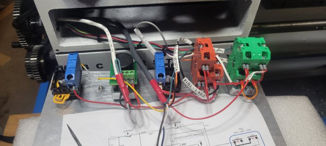
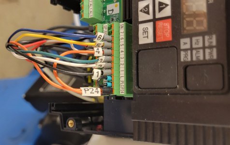
Also the values of the intelligent inputs are assigned there, but you may also see the values in the image I posted earlier of my VFD input labels. I think they were #7 for the Reset, #4 for USP, #6 for Reset, #5 for EXT, as well as the standard #s 1, 2, 3 for forward, reverse, jog.

The pdf Part 2 file that I uploaded should be searchable. Just search for "BRD" or "b097" and you should see the e-brake value listed as 50 Ohms rather than 35 Ohms. In the software you will want to search for "C001" to "C007" to change the intelligent input functions. The active states are changed at "C011" to "C017".

PS. I initially found the VFD programing software to be a little obtuse, but once I got the hang of it it was easy and reliable. I reprogrammed the VFD multiple times. I just used my day to day laptop which was running Win7. (It still is, as I have other, very expensive, software that will not run on Win10 or 11! I also have laptops running Win10 as there is newer software that will not run on Win7.)

In the end, many of my VFD settings are not much different from what Mark had described. His pass postings about the VFD were helpful and reassuring. Figuring all of the VFD info out using the 600+ page manual was a bit tedious, but I think I read it all more than once!

Dave L.

PS. If you do not find the programing table at the end or my Part 2 document let me know and I will post it here or message me with your email address and I will sent it to you directly.
https://www.hobby-machinist.com/att...-vfddescript-links-dnl-l910_1440b-pdf.378083/
 
Back
Top