PM1440-2SM VFD conversion

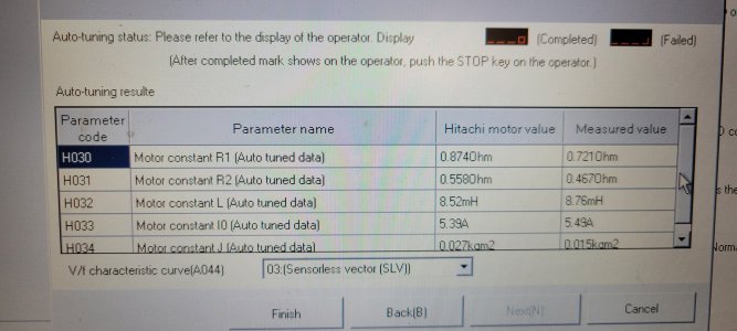
Brake resister ohms is generic, it is not specific to the actual resistor attached. software is buggy, other VFD manufacture's software is much better as well as updated. Had problems with the software years ago and spoke to the US Hitachi rep. said change was very slow over in Japan. A few other parameters are different when using the VFD keypad vs. software. Motor overload is % on keypad, Amps via software and a few other things.
 
Got the motor, powered it up sitting on the floor. Everything seems to work as intended. Can't really check dynamic braking without any inertia - motor stops almost instantaneously in either switch position.
Looks like the 100 frame motor I got will fit, tight, but OK. I need to make adapter plate from existing 90 mount to 100 frame. Will use 1/2" steel plate for it.
Also, need to modify motor pulley, bore from 24mm to 28mm and re-make a keyway. With lathe disabled would have to do it on the mill.
After mounting everything would have to measure distance between pulleys and get a new belt. Currently lathe has 350J12 poly V belt. I'm estimating probably 370 to 380. but have to wait for final install.
 
Made adapter plate today and installed the motor. All wired up and working fine. Performed VFD auto tuning. I expected VFD would automatically use auto tuned parameters after I selected H002 = 02 to use auto tune data. But I still had to change parameters H031-034 manually, they remained at defaults.
Calculated required belt length at both upper and lower range of adjustment - 36" min, 37" max. Ordered two belts, one 36" the other 36.5". Existing belt was 35". BTW, new motor and pulley doesn't interfere with cover, it even has about 1/2" to 1 " clearance ☺.
Mike
 

Attachments

  • 20240410_144918.jpg
    20240410_144918.jpg
    336.3 KB · Views: 22
  • 20240410_175346.jpg
    20240410_175346.jpg
    599 KB · Views: 23
  • 20240410_164345.jpg
    20240410_164345.jpg
    374.7 KB · Views: 24
  • 20240410_155434.jpg
    20240410_155434.jpg
    319.6 KB · Views: 21
  • 20240410_154959.jpg
    20240410_154959.jpg
    371.2 KB · Views: 23
  • 20240410_154946.jpg
    20240410_154946.jpg
    342 KB · Views: 22
  • 20240410_145011.jpg
    20240410_145011.jpg
    513.9 KB · Views: 26
Update - belt installed, and lathe is running just fine. I can't believe how quiet it is now compared to the original single phase motor!
Before I could feel and hear vibration and noise, and it definitely affected surface finish. Now it is very smooth and quiet. I ran it up to 2000RPM+, no turning yet, just idle.
The 36" belt I got is a little tighter than I would like. The longer 36.5" belt will arrive next week.
I want to thank everyone for the help with this conversion.
Mike
 
Happy for you! Congratulations. :)
 
Thanks! BTW, I'm copying your magnet ring for tach. Thanks for the idea. Using aluminum, just because I had it. Planning on gluing magnets in and then put the ring on the spider with blue loctite. It is a close sliding fit.
 

Attachments

  • 20240413_192257.jpg
    20240413_192257.jpg
    457.6 KB · Views: 22
  • 20240413_232153.jpg
    20240413_232153.jpg
    249 KB · Views: 19
Looks very nice! Also nice to know that someone might copy it! :)

I primarily made this so that I could do more accurate spindle rotation counting. But it, provides both this and RPM x 10 signals

Since the Hall Effect sensors are in a unknown metal housing (non magnetic stainless or plastic would be best), I was uncertain as to the effects of putting the magnets inside a metal. I thought Eddy currents via the field reflections between a metal holder and the sensor housing might exist which would limit the distance the magnets magnetic fields extended towards the sensor. If the Hall sensor has no conducting materials then the non-magnetic Al in the magnet holder would have no effect. So to be safe, I used the Nylon that I had in stock (scrap 4' x 4' x 1" sheet from a second hand store) for the magnet holder.... rather than metal. The glue and LocTite should be fine to hold the magnets and the magnet holder to the spider. I trapped the magnets from moving along the slot direction via small wooden dowels on each side of the magnet and then use a nylon screw to keep them down in the slot. Afterwards, I covered the magnets with a thin piece of sheet plastic, which the screws hold in place. I figured this would not hurt anything and it might keep some debris off of the magnets... if there was any. I used a split ring holder and screw to clamp to the spindle. I certainly did not want to glue the holder to my spindle! Besides, the Nylon is not pure and I am not for sure what else is in it. Glue might not stick so well to it. I do not have a spider yet,, so I figured I could turn the center outward to fit to an unknown spider dimension.... someday.

Make sure you insert the magnets all in the same direction (North-South) before gluing.

I am not for sure if you used the drawing my VFD conversion write up to know how I built the magnet holder. There are more pictures at the following posting about a backer board that I also made from the scrap Nylon:
I recently posted my description of my PM1440GT lathe VFD conversion. https://www.hobby-machinist.com/thr...tronic-components-pm1440gt-vfd-3-phase.95058/ ( VFD conversion via solid state electronic components. PM1440GT, VFD, 3-phase )
In this I showed a 10 magnet Hall Effect RMP sensor set up that I machined on a backer board that I made.

I worked in the field of magnetism and magnetic materials a large portion of my career, but I am fascinated by the action at a distance! You might also be interested in this little magnetic device I built...
I recently mentioned that I had built a MAGNETICALLY ACTUATED GARBAGE DISPOSAL several years ago and @francist ask that I post it.
I never never thought to post this to HM as I did not think it was a machinist topic, but ...


Dave L.
 
I changed my mind and instead of using stand alone tach readout decided to use Aikron A30 DRO head. I have Aikron DRO on my mill and like their interface much better than the one came with PM. Nothing wrong with it, I just used to the Aikron interface, and working with PM DRO was not as smooth. Aikron comes with Hall sensor, has additional DB9 input, and RPM readout directly on the screen. It has user changeable number of magnets parameter in the settings, I set it to 10 and have 1:1 RPM reading. It works with PM scales without any rewiring, but I had to set resolution on X axis.
Mike
 

Attachments

  • 20240418_195529.jpg
    20240418_195529.jpg
    352.2 KB · Views: 23
  • 20240418_195558.jpg
    20240418_195558.jpg
    310.2 KB · Views: 20
Hi Mike, The magnet holder looks nice. When I first looked at the photo I could not figure out why the center was black until I realized I was looking down the bore at the closed chuck jaws! I look forward to seeing how you mount your spider.

I looked at the manual for your DRO, but I did not see what I was looking for. Do any of the Aikron heads have a facility(connector) to provide an output signal when a pre-programmed position is reached? It seems like a trivial thing to add to any DRO, but I have not seen it done. If it were there one would not need a proximity sensor system to stop a lathe. One could just let the DRO provide a signal to tell the machine when to stop moving the saddle, i.e. turn off the spindle power.
 
Dave, I don't think they have any with position output. You may try to contact them with this request. I understand they build and program their DROs per order. I had one for mill ordered with 3 axis, tach input, and probe input. DRO for lathe I ordered with 2 axis and tach input only. They take some time, 5 - 6 days after order to actually ship it. That's why I think they build per order. This may allow them to do more custom features, especially if it did not require hardware changes other than adding connector. I had email exchange with them for some technical question and was getting reply very fast considering time difference between us.
Mike
 
Back
Top