PM1440GT Is in the shop!

LVLAaron

Registered
Registered
Joined
Oct 4, 2020
Messages
484
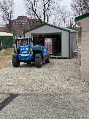
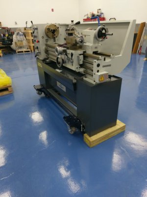
It took 4 months longer to get here than it should have. I followed the Ship that was supposed to land on the west coast get re-routed to the east coast and sit in the water for ages. Anyway, she's finally here.

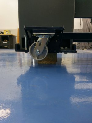
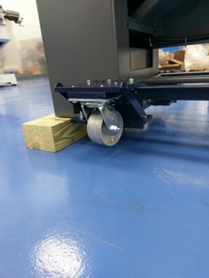
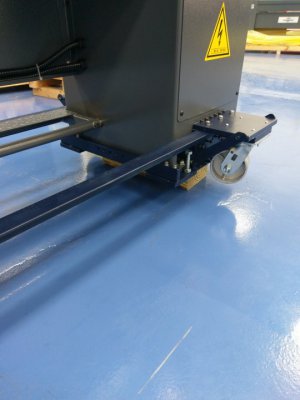
The palleting (is that a word?) Definitely needs to be re-worked from the factory. If you're on the skinny side, you can only get half way under it with the forks, which makes it tippy. If you're on the wide side, you can only get forks under it towards the center, so it's super tippy.

The Freight driver was super helpful and interested in what I had going on and offered to help guide me in, he didn't have to do that... thanks dude, much appreciated.


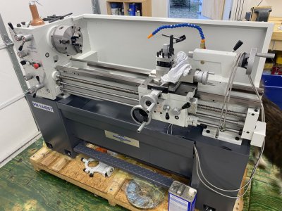
This is a 3 phase model I'll be doing a VFD conversion on. I am pretty sure I have all of the parts and widgets needed, as well as a local friend with the same setup... I'll do my best to keep this thread updated with progress.
 

Attachments

  • 22-01-27 12-36-11 6885.jpg
    22-01-27 12-36-11 6885.jpg
    159.3 KB · Views: 236
  • 22-01-27 17-28-18 6888.jpg
    22-01-27 17-28-18 6888.jpg
    168.8 KB · Views: 246
Congrats. I ordered mine on the 13th. Going to be a long wait.
 
Congratulations!

If you did not see my posting, I finished the write up on my PM1440GT VFD conversion last year. I took a more modern electronics approach to the design and so EVERYTHING fit in the back of the stand where the original electronics were located with room to spare. You can see a photos as well as documentation, Part 2, at this link. I think this design incorporates all of the features and safety ever discussed on HM plus some extra ones. If you are planning to follow the common path found on HM, which mostly uses the original bulky electronics, but which will not fit in the lathe stand easily then you may still want to look at my Part 1 description and drawings of how the factory relays etc. are wired up.
VFD conversion using solid state electronic components.
If you are interested in my approach I would be happy to help by answering any questions.

PS. I also put mine on steel casters so that I could move it around if ever needed. After it is where I want it the bolts screw down for leveling and raising it off of the casters. They work nice, but the mounts could have been built easier than the approach I took. However, I did not have it in my possession when I designed and built the casters.

PPS. Currently, I am working on an Excel spread sheet which will automatically generate ALL possible TPI and FEED rates of the lever, knob and external gear settings and put them into a table. I was going to do this by hand, but it turns out to be a lot of them. I figure about . If one includes all of the external gears that comes with the lathe and the possibility to do threading using the Apron Feed lever rather than just the split nut TPI lever there appears to be over 6000 of them with some redundancy. Hence, there should be no thread that you should not be able to approximate, English or Metric. You should check and see if you got all of the gears as well as all of the other accessories (see the manual for the list). I will post it when I am finished with it.

Dave L.
 
They're so pretty when they're new! Enjoy it! I'm sure you'll be unintentionally making me feel inferior in no time with that beauty. Lol
 
@LVLAaron

Sorry if my message was not complete. Since you edited/removed your post maybe you found the Quote link that I provided to the VFD conversion in my first post. In case you did not, you can find it HERE . The Part 1 and Part 2 that I referred to are attachments there.

If you look in the photos inside the Part 1 attachment you will see a photo of the lathe on the Casters. However, I never wrote up my caster build. If you are interested in the caster build I can provide details, even some detailed drawings, but if I were to make them over I would make them more simply and would probably weld up the parts and not do so much machining of parts. I would then bold them to the sides of the lathe stands rather than attaching them to the bottom via new plates. I did take a number of pictures and will attach a few of those pictures here. I did not have a good idea of how strong the stands were so I designed the casters to be attached to a plate which bolted under the lathe through the original leveling feet holes, which by the way has a screwball Old English thread to it. (So, I used these feet bolts to attach the plate to the stand bottoms and made new leveling feet holes in this plate.) I so I was concerned that the lathe attachment to the lathe stands might not be strong so I attached the caster mounts together by a couple of pieces of angle iron running from end to end. These are not really needed, but make is stronger. The front one is a bit in the way of the foot brake but can be removed via a few bolts. After the VFD install I find I never use the foot brake anyway. This all makes the caster built more complicated than necessary. I could have done it more simply if I had the lathe and a way to easily lift it. Hence, I never posted the build.

I live in Pittsburgh, PA so I went to the PM shop and assembled and mounted the casters onto the lathe there. Hence, when they delivered the machine to me it was already on the casters. We put it in my basement and just rolled it through a small crooked hallway into a small room which I use for metal machining for its final install location. Tony and all (PM) were very helpful. We even made a short video of Tony pushing the lathe around. It is very strong and does not wiggle on the stands at all when rolled around. I was going to post the video, but felt it should be edited to remove the sounds first. I needed some video editing software I did not have so it never happened. By the way, I did not know at the time, but later Matt (PM) told me that I could have simply loosened the bolts holding the lathe to the stands to move them around a bit. The stands were not exactly square to the lathe!

As far as the Excel TPI spread sheet I have yet to finish it, but I will post it to HM when I do. It is being written in sort of a general format so that it could be used to generate TPI tables for other lathes as well.

Hope this helps to explain things better.

Dave L.
 

Attachments

  • IMAG2227.jpg
    IMAG2227.jpg
    128.3 KB · Views: 187
  • IMAG2231.jpg
    IMAG2231.jpg
    122.3 KB · Views: 150
  • IMAG2235.jpg
    IMAG2235.jpg
    58.1 KB · Views: 150
  • IMAG2237.jpg
    IMAG2237.jpg
    45.2 KB · Views: 148
  • IMAG2240.jpg
    IMAG2240.jpg
    54.5 KB · Views: 134
  • IMAG2243.jpg
    IMAG2243.jpg
    50.6 KB · Views: 180
Congrats!

After you complete the conversion, what will you make first?
 
A gear chart was done previously for the 1440GT in a previous thread, it has pull downs for the different gear combinations.
 

Attachments

  • PM-1440GT Change Gear Thread Calculator.xls
    39.5 KB · Views: 129
Back
Top