PM1440GT Is in the shop!

I did run a 4 wire service to my lathe.
We were thinking a like. I ran the 4 wire connection directly from the wall breaker box to a wall knife switch box and then straight on to the lathe stand back enclosure, where I put all of my entire VFD build including the braking resistor. Both the Coolant power (220V) and the DRO (110V) then come directly from the lathe stand enclosure. No external enclosure nor external connections except between this enclosure, the front panel and of course the motors and sensors.

in their factory location for now.
Two locations......Take care to carefully shield all of those control wires running between the two cabinets and keep them neat. This is where the interference and noise can kick in if you are not careful. In general, in electrical engineering best practices, the shorter the wires... the better for interference and noise immunity. Also, try not to run high current carrying wires parallel or in close proximity to the low current signal wires.

Dave L.
 
We were thinking a like. I ran the 4 wire connection directly from the wall breaker box to a wall knife switch box and then straight on to the lathe stand back enclosure, where I put all of my entire VFD build including the braking resistor. Both the Coolant power (220V) and the DRO (110V) then come directly from the lathe stand enclosure. No external enclosure nor external connections except between this enclosure, the front panel and of course the motors and sensors.


Two locations......Take care to carefully shield all of those control wires running between the two cabinets and keep them neat. This is where the interference and noise can kick in if you are not careful. In general, in electrical engineering best practices, the shorter the wires... the better for interference and noise immunity. Also, try not to run high current carrying wires parallel or in close proximity to the low current signal wires.

Dave L.

I have an assortment of shielded wire from automation direct for the control stuff. Is there any kind of foil/wrap/tape I could/should use on the line voltage stuff?
 
It took 4 months longer to get here than it should have. I followed the Ship that was supposed to land on the west coast get re-routed to the east coast and sit in the water for ages. Anyway, she's finally here.

The palleting (is that a word?) Definitely needs to be re-worked from the factory. If you're on the skinny side, you can only get half way under it with the forks, which makes it tippy. If you're on the wide side, you can only get forks under it towards the center, so it's super tippy.

The Freight driver was super helpful and interested in what I had going on and offered to help guide me in, he didn't have to do that... thanks dude, much appreciated.


This is a 3 phase model I'll be doing a VFD conversion on. I am pretty sure I have all of the parts and widgets needed, as well as a local friend with the same setup... I'll do my best to keep this thread updated with progress.
Congratulations on getting your lathe.
I am curious to know when you ordered your lathe. I ordered my 1440GT the last week in October. They gave me a mid February date for delivery. Now they are telling me mid March or April.
 
The line voltage wires to the VFD as well as from the VFD to the motor are carrying significant currents. However, most of the noise and interference are inductive and are caused by the sudden changes in the current. The VFD drives the motor with pulse width modulation and so these are the critical wires.... from the VFD to the 3phase motor. I do not know your physical configuration, but assume that the enclosure containing the VFD will be only a few feet from the motor. (A wall mount or mounted to the outside of the lathe stand somewhere?). The electromagnetic fields generated by these currents in these wires radiate outward and when they reach a conductor (shield) they create currents in the metallic shield. The thickness of the shield material needs to be at least the thickness of what is called the electrical "skin depth." The skin depth goes as one over the frequency (harmonics of the switching currents time rate of change) of the changing current. It also goes as 1/the conductivity of the shield material. For high frequencies this is not to large so the metal thickness does not have to be very large. A thick aluminum or copper foil will do but it should be grounded somewhere preferably near the motor or near the VFD, but in concept it does not have to be grounded at all. A heavy gauge Al foil will work if you can make a ground to it. A steel covering will also work, but will need to be thicker as its conductivity is not nearly as good as copper or aluminum. It might be easiest and the best to use a flexible steel conduit hose. This would also physically protect the wires, especially if they are individual wires. I cannot recall at the moment, but I think the wires can carry as much as 20 Amps to a motor under full load from the Hitachi 3HP VFD so that would be a 12 gauge stranded wire or larger. If you web search on "metallic flexible conduit" you will see lots of examples. The trick is to find a short piece so that you do not pay much. Even Home Depot / Lowes or most electrical stores carry this, usually in steel and but sometimes in aluminum and sometimes they will cut a piece off for you. Then you will need strain relief connectors at the ends.

If you go the foil route then you could wrap a small bare wire around the foil and keep it pressed against. The problem with this is that the bare wire really should be made from the same material as the foil to prevent chemical reactions.

If we did not live so far apart I would just hand you what you need as I have lots of this stuff.
 
PS. Forgive me if you are already familiar with wiring.... If you look at my VFD conversion photos you will see the yellow cable I used to bring the line voltage to my lathe. At the entry point into the lathe stand you will see the 90 degree strain relief that clamps the wire to the metal stand. It has nut on the inside holding it to the stand. The yellow cable is something that I picked up years ago and I finally found a good use for it. It has 4 rubber insulated stranded 10 AWG wires inside the yellow rubber case. Good stuff. I am glad I did not have to go out and purchase it. It is nice and flexible and so I can roll my lathe out from the wall to work on it without worrying about breaking the wires or taking the wires loose.
 
Hi Mark, @mksj

Sorry to post this here, but ... since you provided a link to @jbolt 's TPI chart at this string I assume you will see this. One does not usually need to know that power feed rates very well, but for what I am working on I would like to have it.

Would you have an accurate "power feed" rate for the PM1340GT that you can share with me. When I looked at the manual, and so the picture of the lathe plate, it gives numbers which are all over the map and only really accurate to one digit. It does not actually say what the power feed rate is for any gear arrangement in the manual. It just refers to the lathe plate. Hence, I have insufficient data or info to deduce the apron (power feed) gear ratios. Likewise, the manual does not provide any accurate internal gear descriptions, but as your TPI spread sheet shows one only needs to know a few of the TPI values for the standard 40T-40T external gears to deduce the internal gear ratios (not the number of teeth on individual gears). (I did not see any power feed rates on your spread sheet, only the threading feed rates.)

If you do not have it maybe @davidpbest or someone else knows the answer. ?? I think he also has a PM1340GT and shared a Threading TPI chart for his lathe.

While the manual and the lathe plate for my PM1440GT provides power feed rates I was able to actually measure them more accurately. I simply let the power feed move the apron a long distance (~20 inches) while I used the 10x spindle counter (and the proximity trip to stop the lathe) that I included in my lathe panel to measure the number of turns accurately. I then took the change in the DRO distance reading and divided by the number of spindle turns to get a power feed rate. This was accurate enough (~ 5 digits) to actually determine a set of gear teeth counts in integers for the gear teeth numbers for the apron. (28/(25*38)) I suppose one could even do the same, but not nearly as accurate, by knowing a constant spindle RPM and measuring the time it took for the apron to travel a known long distance. Anyway, this would probably be more accurate than the one digit numbers on the PM1340GT lathe plate!

Thanks.

Dave L.
 
The answers are corked up in the attached, and it all has to do with the change gear combinations. At least for the 1340GT.
 

Attachments

  • PM 1340GT Gear Chart.xls
    82.5 KB · Views: 73
Hi David, @davidpbest

Thanks David, but I don't think I was clear, the z axis motion that is referred to in the spread sheet you attached is using the split nut lever which engages the lead screw (see descriptions: "Thread to thread in" and "Thread to thread mm"). These are simply the 1/TPI values. These values are not from the power feed lever which I think produces a much slower motion of the apron. The "power feed" lever moves the apron from the slotted rod not the lead screw. The apron gears for this power feed lever are different and so the feed rate is usually much smaller. It is on the PM1440GT.

If you look at the lathe Thread Chart plate, also shown in Figure 3-7 of the PM online PM1340GT manual you will see in the center of it a column that lists as power feed rates for the apron as well as for the cross slide (inches). They are not written out with any accuracy. Just compare them to the cross feed rates as well as to simple factors of 2s. Hence, I am trying to find a more accurate number. They do not depend upon your gear selection lever on the right (1,2,3, ...8) but do depend upon the left gear selector lever (A, B, C, D, E) so increments in factors of 2x only. In side the gear box, the gears associated with the A, B, C, etc selection drives the shaft that and gears that link to and turns the slotted rod. The transfer gears that are on this rod connect to another set of gears on a shaft that is above this one and which is connected to the lead screw ... for threading.

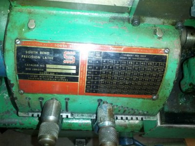
On my 1440GT the gear selection levers has an extra position called "I". It moves the lead screw gears to a position which is disengaged from the transfer gears on the slotted rods shaft. So when in the "I" position the lead screw does not turn but the slotted rod does and one can do Power Feed without turning the lead screw. I am not for sure why this feature is different between the lathes or why the 1440 needs to work this way but it maybe to allow one to do feeding without wear on the lead screw, split nut nor the lead screw and power feed gears, but even though your lead screw always turns you do not have to engage the spit nut to feed! So you can avoid wear on your split nut and leadscrew by just not using them for feeding. The lever setup on your 1340 is more like my old South Bend 10 (attached photo) which does not have a slotted Power Feed rod at all, but has a lot more threading options than the 1340GT. The SB10 has 10 fundamental threads with its lever selections and then there are 7 factors of 2. While the PM1440GT, with its two levers systems, is set up considerably different from the 1340 it has 16 fundamental gear selections. However, a number of them are not the standard threads and there is even a duplication of the 4TPI value, but worst thing is it is missing the 6TPI which means it is missing the standard 12TPI without using the external gears. The first set are: 4.200, 5.600, 7.000, 4.582, 3.000, 4.000, 5.000, 3.273, 2.400, 3.200, 4.000, 2.618, 4.125, 5.500, 6.875, 4.500.

With 7 factors of 2 and 10 fundamental threads the SB actually has the best set up for standard threads. It even has a position for 480TPI! I have yet to see anyone make such a thread, but it is very slow feed rate.

Thanks again.

Dave L.
 

Attachments

  • IMG_20170625_181510.jpg
    IMG_20170625_181510.jpg
    167.5 KB · Views: 64
Sorry I misunderstood. On the 1340, you can move the carriage via the threading lead screw using the half-nut to engage, or you can advance the carriage via the slotted feed rod. The spreadsheet I posted is mostly for the leadscrew. That said, the ratios of the Norton gearbox which drives the slotted feed rod are, I believe, embedded in the spreadsheet. I didn't author that data set - Mark Jacobs came up with the original. You might want to check in with him (@mksj). Sorry for the confusion.
 
The line voltage wires to the VFD as well as from the VFD to the motor are carrying significant currents. However, most of the noise and interference are inductive and are caused by the sudden changes in the current. The VFD drives the motor with pulse width modulation and so these are the critical wires.... from the VFD to the 3phase motor. I do not know your physical configuration, but assume that the enclosure containing the VFD will be only a few feet from the motor. (A wall mount or mounted to the outside of the lathe stand somewhere?). The electromagnetic fields generated by these currents in these wires radiate outward and when they reach a conductor (shield) they create currents in the metallic shield. The thickness of the shield material needs to be at least the thickness of what is called the electrical "skin depth." The skin depth goes as one over the frequency (harmonics of the switching currents time rate of change) of the changing current. It also goes as 1/the conductivity of the shield material. For high frequencies this is not to large so the metal thickness does not have to be very large. A thick aluminum or copper foil will do but it should be grounded somewhere preferably near the motor or near the VFD, but in concept it does not have to be grounded at all. A heavy gauge Al foil will work if you can make a ground to it. A steel covering will also work, but will need to be thicker as its conductivity is not nearly as good as copper or aluminum. It might be easiest and the best to use a flexible steel conduit hose. This would also physically protect the wires, especially if they are individual wires. I cannot recall at the moment, but I think the wires can carry as much as 20 Amps to a motor under full load from the Hitachi 3HP VFD so that would be a 12 gauge stranded wire or larger. If you web search on "metallic flexible conduit" you will see lots of examples. The trick is to find a short piece so that you do not pay much. Even Home Depot / Lowes or most electrical stores carry this, usually in steel and but sometimes in aluminum and sometimes they will cut a piece off for you. Then you will need strain relief connectors at the ends.

If you go the foil route then you could wrap a small bare wire around the foil and keep it pressed against. The problem with this is that the bare wire really should be made from the same material as the foil to prevent chemical reactions.

If we did not live so far apart I would just hand you what you need as I have lots of this stuff.

Appreciate the info. I'm familiar with electrical and electronics (I've wired homes, built custom PCB's for adruino projects, etc etc) I don't know everything, but am following what you're telling me.

My box will be mounted on the lathe so my runs will be as short as possible. I've got everything I need except the flexible conduit.


I spent the day yesterday going over the wiring and making sure I understand how it's all plumbed. The document attached is what I am using as a reference. (I wish I could credit/remember which user created the doc)


Today I'm getting the VFD drivers and software loaded up, and will start reading about how it fits in the picture. Stuff like how to integrate the foot brake switch is still a bit unclear.
 

Attachments

  • PM1440GT Basic Wiring Changes for using the Contactors to switch the VFD inputs 23 DEC 2018.pdf
    4.8 MB · Views: 87
Back
Top