pm25-mv z axis power feed

Went thru those threads. Think the mobile home slide out motor is bit overkill? and not sure i want metal gears.

Have seen two speed wiper motors- so if have enough torque might be good for elevating/lowering head of a 25?
And two speeds would be nice.

Have also seen quite a few other applications of wiper motors for power tools, robots --- and this price is good, and worth a first try:

https://www.ebay.com/itm/Super-Auto...m=281349810237&_trksid=p2047675.c100752.m1982


As far as gears, the fly wheel nylon 1/2" may do to start:

https://www.ebay.com/itm/10-STARTER...699073?hash=item3ac3f4bb81:g:1LoAAOSwbcJXPf3K

My plan would be to epoxy/bolt two together for a 1" wide gear, and cut shafts for them to fit the motor shaft and Z drive wheel axle. At this price, can afford to experiment.

Have also seen these timing gear/pulley with belt setup if need reduction:

https://www.ebay.com/itm/XL-30-10-T...e8:m:mPy0eXcQW3kGazMTQDCnS-w&var=561427337655

Going to start thinking wiper motor has enough torque on 1:1 gear ratio. If not- then back to the ebay..

Plan on using the same type of motor for lateral table drive, with a single control box with switches and central power.

have to see----
 
I have always believed that there are a 1000 ways to do something. That's what makes a hobby interesting!! You've got some solid ideas to work with and I'll be interested in your progress.

I have the metal change gears on my Craftsman lathe and they are a bit on the noisy side, but for this application I don't think it would really make any different whether the gears are metal or nylon/plastic. As long as the gibs are adjusted and the ways lubricated raising and lowering the head should be a smooth operation with little strain on the gears.

I wonder that the output speed is on the wiper motors?? I don't think I would be happy with anything less than a 100 RPM's. 150 would be ideal from what I am seeing with my setup. Two speed might have it's advantages too, and depending on the output speeds make it easier to be flexible with available gearing.

I can see using the pulley belt setup. You could still keep the installation compact like what I have, and if you can find different pulleys for changing the ratio it would be a breeze to change.

I had thought about a lateral drive, but haven't really needed it for the small pieces that I have been working with so far. Once set in the vice, I only have to move the table 2-3 inches to make my cuts. I'm now thinking that unless I decide at some point to add a CNC capability and tackle that learning challenge, I'll just leave it manual.

Take lots of pictures as you work through your mod. I'll be following with interest!! :geek:
 
Only thinking of the nylon flywheel gears because they are an inexpensive stock item that can be replaced or purchased by someone wanting to duplicate after the mechanism following the thread. Also, since they can operate a flywheel they may be a bit more wear resistant than gears designed for other applications.

I have also seen these 12v DC motors used for diy applications, including lateral motor drive for mini-mills.

Geared for number of different RPMs- and no load torque is indicated as:

* Load torque: 10KG.CM
* No-load speed choice : 0.6RPM/2RPM/3RPM/10RPM/25RPM/100RPM/120RPM
* Self-locking worm gear motor, ie., output shaft will not move w/out electric current.


https://www.ebay.com/itm/12V-DC-Mot...c2:m:mss6yV43zYgQ8HOH4CvVOqA&var=621520808302

-----
Not sure how to flintstone the PM25 Z-drive to see if it needs more than 10KG/cm- so might risk $7- 14?
 
The motor I used is rated at 2.2 ft lb's or 26.4 in lb's or torque. The crude test I ran for a minimum torque to lift the head was somewhere around 15 inch pounds. My brain goes 'TILT' every time I have to convert imperial to metric.... so I'll let you do that!! I'm not sure if it's a product of low voltage, low torque or low speed that makes it seem like my setup is working as hard as it can.

The voltage rating on the motor is 13.8 VDC and my power supply which is a 12 volt supply sold for driving LED's actually has a load voltage of about 11.8 volts. I haven't checked to see how many amps it actually takes but the supply is rated for 30 amps. These power supplies from China are junk in my opinion. They have a voltage adjustment but it has a very small adjustment range and won't get to the 13.8 needed.

I was ordering some drill rod from Speedy Metals online last night and noticed that they carry nylon round stock as well as another high strength plastic. I may look into adding a dividing head and cutters for making these gears on the mill or my lathe at some point. On my bucket list anyway. The nylon that Speedy sells is rated high for machinability so it should be pretty easy to work with.
 
To prevent further brain 'TILT' to convert imperial to metric use this simple online calculator:

http://www.onlineconversion.com/torque.htm

---
I get:

2.2 ft lb = 30.42 kg cm

15 In lbs = 17.28 kg cm

Motor rated at:

10 kg cm = 8.68 in lb or 0.723 ft lb

So a little shy of your 15 estimate, if the calculator was calculated correctly?
1:2 gear reduction might hit your estimate, but cut the rpm down to 50?
 
The motor I used is rated at 2.2 ft lb's or 26.4 in lb's or torque. The crude test I ran for a minimum torque to lift the head was somewhere around 15 inch pounds. My brain goes 'TILT' every time I have to convert imperial to metric.... so I'll let you do that!! I'm not sure if it's a product of low voltage, low torque or low speed that makes it seem like my setup is working as hard as it can.

The voltage rating on the motor is 13.8 VDC and my power supply which is a 12 volt supply sold for driving LED's actually has a load voltage of about 11.8 volts. I haven't checked to see how many amps it actually takes but the supply is rated for 30 amps. These power supplies from China are junk in my opinion. They have a voltage adjustment but it has a very small adjustment range and won't get to the 13.8 needed.

I was ordering some drill rod from Speedy Metals online last night and noticed that they carry nylon round stock as well as another high strength plastic. I may look into adding a dividing head and cutters for making these gears on the mill or my lathe at some point. On my bucket list anyway. The nylon that Speedy sells is rated high for machinability so it should be pretty easy to work with.
-----

Note : Speedy Metals price is $35. per foot plus shipping for 1.5" nylon round stock? I'm going with nylon flywheel gears... Free shipping
 
It's been a while since I updated this thread and I am now nearly finished with the mod. To start off the nylon gears that I picked up had to be resized to fit the 3/8" motor shaft and the 5/8" mill crank shaft. Here I have turned an aluminum insert to fit. After knurling and using some handle grip cement the insert was pressed in and bored for the slip fit on the 3/8" motor shaft.

The set screws were taps for 12-32 and set screws installed and the excess was cut off and faced.
View attachment 269619

The support frame was cut and machined for a nice square fit. Notice that there is a 1/8" lip on the end pieces to make it easy to align for welding.

View attachment 269620
Mock up with the support taped together.

View attachment 269621

After welding assembly is started.

View attachment 269622

Original crank is removed.

View attachment 269623

12 volt power supply is mounted to the wall abd motor assembly is trial fit on the mill.


View attachment 269624
I decided on a spring loaded momentary ON-OFF-ON rotary switch and picked up a perfect box from Amazon. I wanted the box to mount at an angle so used a couple of cabinet hinges to mount. Later I locked the hinge in this position and used JB Weld to make it somewhat permanent.
View attachment 269625

I've got the project running now and it works flawlessly. I'll get some updated pictures later.

The motor output speed is 100 RPM and with the gears 1:1 movement is a nice steady 4.25 inches per minute lifting, and 5.58 inches per minute lowering. The motor seems to have plenty of extra torque and runs nice and quiet. It's taken me quite a while to finish the project because of health limitations, but well worth the effort.
----
Question-----


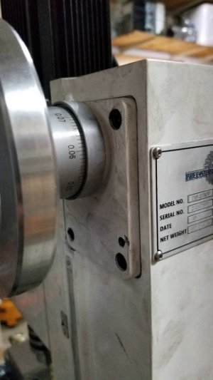
Did you remove the plate holding the shaft for the crank handle that bolts to side of the column? Or bolt your motor mount box to the plate while it was still attached to the column?

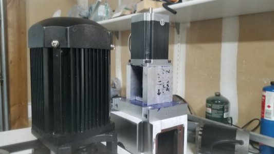
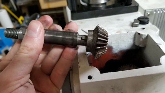
Looking at pictures from another post, it appears that the crank handle shaft is held in place by the boss attached to the plate. (these again are pictures from another post on the forum). Removing this plate would make your motor mount wobble?

I assume that the crank handle shaft is held in place and alignment by the plate, and your "fabricated box" was attached to the outside of this plate with longer countersunk bolts. It appears when the unit is CNC'd, that the vertical threaded shaft is replaced with ball screws/shaft and alignment occurs from above, and this crank handle plate is replaced with a blank. pm25 5.jpgpm25 6.jpgpm25 4.jpg

I am also thinking of using two large pieces of angle iron (4x4x.25) that bolt together in an overlapped fashion on the top rather than fabricating a welded box. Will need 3 or 4 bolts on the top to secure the two overlapped legs together, but then would be easier to mount the wiper motor (than you did from inside), and could unbolt and change the wiper motor angle iron plate side
pm25 5.jpg
pm25 6.jpg
pm25 4.jpg
if wanting to change motors or gear dimensions. (again just a conceptual pre-thought).
 

Attachments

  • PM25- wiper motor mount bracket.pdf
    505.6 KB · Views: 102
You're right about using longer screws and attaching my box to the outside of the original plate. I didn't want to modify the original column any more than necessary so I ended up with only the 4 screws that hold the switch box. I actually never did even open up the column to look to see what was in side. If memory serves me and without going out to the shop I think the screws are M-6 and about 1/4" longer than the originals. The original plate does hold the shaft in position for proper mesh.

I wonder if the wiper motor mounting bosses are laid out the same as my motor? I previously posted a manufacturer's drawing that gives the dimensions for this one. I wonder if the various wiper motors have somewhat of a standardized bolt pattern?? That would certainly make it easier in the future to try different motors or replace a bad one.

The pictures of the top mounted motor look to me as being over-built. Depending what you have laying around the shop to work with, these motors don't produce a huge amount of torque so mounting doesn't have to be super sturdy.... rigid yes...... but bullet proof Mach Truck design is over kill. My box was also a way for me to try out the machine and test my basic knowledge of milling operations.
 
Yes I figured the crank plate with boss held the crank shaft in alignment, and that only CNC applications could remove the plate with top mounted motor. Those pictures only related to the plate area and what is left when it is removed. looked like that fellow had armor plated material laying around or planned on adding a turbo to the stepper?

I am still thinking of the overlapping angle iron as a short cut if wanting to change motors or gear ratios. The piece of angle iron bolted to the column over the crank plate could stay constant, then only have to drill and bore holes in another piece of angle iron to change things. Presently, I am way behind on this and looking at all the threads and utube videos before cutting or drilling... Have ordered a few things..

Think you mentioned vice size in one thread somewhere? I ordered the 5" but think some prefer the smaller 4" that PM sells? Wish they had mentioned that when I ordered, or asked me to check... I don't plan on the rotary base, but would like the most use out of it without banging into the column...
 

Attachments

  • PM25- wiper motor mount bracket.pdf
    505.6 KB · Views: 117
Back
Top