- Joined
- Dec 18, 2022
- Messages
- 1,675
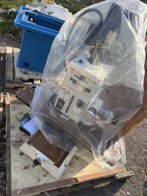
I had mentioned this tool in a previous post and several folks asked me for more detail, I had wanted to drawing and send it out but I have not had the option so I thought I would put photos in a post to get the general idea across.

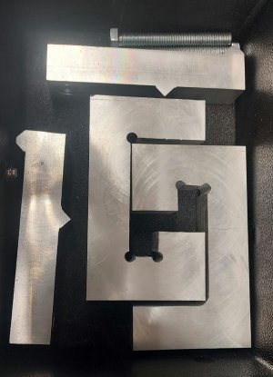
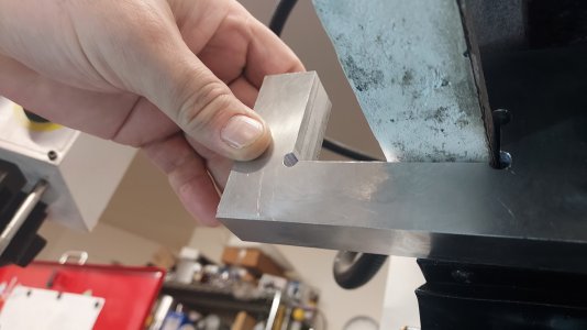
This is the tool as stored, note that there are 2 of each item that is because there will be 1 tool on the left side of the head and 1 on the right hand side. I am only setting this up to show how it works, I not going to tram the mill as it is as I want it. I used aluminum as it is what I had on hand.

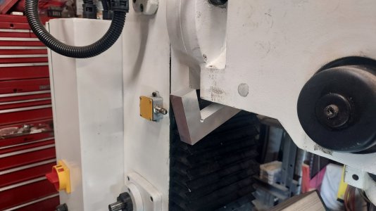
The G shaped piece fits vertically under the head to the rear, it hooks to the lip on the inside of the head as shown.

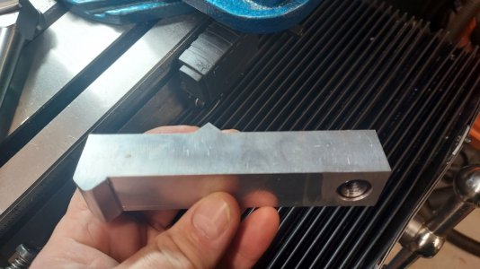
this is the vertical hanging from the inside lip.

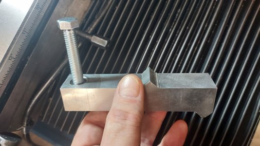
This is the horizontal cantilever beam, it is used to apply the force you put into the bolt, shown in the next photo, to rotate the head left or right. Notice there is a steel insert in the aluminum it is thread locked in place intended to keep the rotating threads from working against aluminum.

Here you see the bolt which will be used to rotate the head.

This photo shows the tool installed on the left hand side of the mill. Note that I place a piece of metal scrap under the bold to avoid causing cosmetic damage to the mill.

This photo shows a top view of the installed tool, note that if I were getting ready to use this tool I would have centered the point on the Horizontal member up with the vertical member. the bolt is pushing on the portion of the head which rides on the ways while the vertical piece holds the horizontal member in place on the rotating portion of the head. If I were tramming the mill I would assemble the tool on the right hand side of the head then put the SST tramming gauges in the quill and look to see how the head would need to move. Once you determine the direction you need to rotate the head loosen the bolt on one side then tighten the bolt on the opposite side to move the head, use small increments. This trams the Y-axis, if you need to tram the nod that will require shims on this mill.

This is the assembled tool as seen from the table looking up, the nut on the stud you see is one of the three you have to loosen to rotate the head. I also found that once I have the head where I want it, before I loosening the bolts on the tools I tighten the bolts holding the head. If I loosen the tools first, tightening the bolts on the head will pull it off from where it needs to be.
I hope this helps....
This is the tool as stored, note that there are 2 of each item that is because there will be 1 tool on the left side of the head and 1 on the right hand side. I am only setting this up to show how it works, I not going to tram the mill as it is as I want it. I used aluminum as it is what I had on hand.
The G shaped piece fits vertically under the head to the rear, it hooks to the lip on the inside of the head as shown.
this is the vertical hanging from the inside lip.
This is the horizontal cantilever beam, it is used to apply the force you put into the bolt, shown in the next photo, to rotate the head left or right. Notice there is a steel insert in the aluminum it is thread locked in place intended to keep the rotating threads from working against aluminum.
Here you see the bolt which will be used to rotate the head.
This photo shows the tool installed on the left hand side of the mill. Note that I place a piece of metal scrap under the bold to avoid causing cosmetic damage to the mill.
This photo shows a top view of the installed tool, note that if I were getting ready to use this tool I would have centered the point on the Horizontal member up with the vertical member. the bolt is pushing on the portion of the head which rides on the ways while the vertical piece holds the horizontal member in place on the rotating portion of the head. If I were tramming the mill I would assemble the tool on the right hand side of the head then put the SST tramming gauges in the quill and look to see how the head would need to move. Once you determine the direction you need to rotate the head loosen the bolt on one side then tighten the bolt on the opposite side to move the head, use small increments. This trams the Y-axis, if you need to tram the nod that will require shims on this mill.
This is the assembled tool as seen from the table looking up, the nut on the stud you see is one of the three you have to loosen to rotate the head. I also found that once I have the head where I want it, before I loosening the bolts on the tools I tighten the bolts holding the head. If I loosen the tools first, tightening the bolts on the head will pull it off from where it needs to be.
I hope this helps....
")