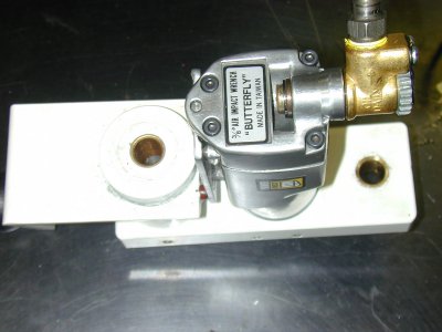
Pneumatic power draw bar on PM932M-PDF

Hi Radek,
thanks for sharing your power drawbar build. I too have a PM932-PDF that I received about two weeks ago. As it turns out, I've had other obligations so haven't had much time on the mill yet. I am a complete novice when it comes to metal working machinery so I read with interest your description of the trials you went through to get your mill working the way you'd like it to.

As far as I can tell without taking things apart, I don't have the contamination or gears binding in the PDF gearbox that you encountered. If I get brave enough at some point I may take the cover off and take a look.

You out mentioned the difficulty tramming the head without an adjustment mechanism to fine tune things. I share your frustration. I will be interested to see what you come up with. I would also be interested in any details you'd like to share about the power drawbar design and build. I have the same issue that DarkZero reported with his original drawbar. The adjustment nut is several degrees out of square and very noticeable. I guess it works OK but it totally bugs me every time I use it so I am going to do something about it when I get a chance. I am leaning toward the power drawbar route. Is it a reasonable project for a beginner?

I should probably mention that I have ordered a PM1236 that should arrive in the next few weeks so I will have access to a lathe too. Anyway thanks for sharing your nice build and the story on your mill. It has given me some confidence that while these machines are not perfect, they are capable of precision with a little effort.

You are welcome Lynrob. Congratulation on your new PM932-PDF. Despite my critical review of the mill I am happy to see you take it in stride and put things in right perspective. I am sure you will find the machine to be a good purchase. For a home use, or even the small commercial enterprise, I do not think you will outgrow it.</SPAN></SPAN>

I know it is easy for me to take things a part due to my trade. However I still stand behind my statement of looking into the feedbox, especially if you will use power down feed. If you turn the power feed selector to off, you will not damage anything even if sand is present as nothing is turning. To take the feedbox of is not a big deal as all you have to do is remove the hex screw on the end of the feed operation handle. Take a note of couple discs. You do not have to remove the individual handle which are retained by knurled pins. If you do, as I did, they are tapered pins and you knock them out with a pin punch. If you remove them you may be rewarded (like I experienced) by a find of insufficient grease which caused both levers to bind. You can take the manual feed handle off. It is basically self explanatory, as if you accidently drop it you don’t brake the handle. Then remove four bolts with 6mm Allen key. Now do not be afraid, just pull the assembly strait out. You may use small sharp chisel with hammer to help you get it started. The feedbox casting has two dowel pins so do not try to twist it off. Don’t baby it too much, under that white paint it is just an ugly piece of cast iron.</SPAN></SPAN>
When you pull it off look at the front edge if you find piece of aluminum strip, throw it in the rubbish bin and read my other post. If unsure send me a private message. I will help you over the phone. If not see that the mating surface is clean. There is no gasket, unless of course they made a shim to fix their screw-up. Look at the gears, scrape some grease off and rub it between you fingers. If you feel no grid reassemble it in reverse process and be happy. If you feel grid, take it all apart and I mean all, including the bearings and wash it in the solvent tank. Advertisement indicated that all bearings are sealed for life. There is four of them and only one included dust shield. Rest were open ball bearing full of gritty junk. Dump then in the solvent tank except the ones that have a dust seal. Should your machine suffer from same sand syndrome as mine one of the most difficult pieces to disassemble was the change “gear lever set” item #22 in the owners manual. The second irritating pieces were part of the clutch and tiny little springs #14, 17, 68 and 19. Take your time with the little springs, forget about the time, go for walk, what ever, just do not bend them or damage them, I would think they are quite critical, unless of course Matt has them in stock, they would be somewhat hard to find. The whole process is not a black magic. Figure out what each part does and you will be rewarded with knowledge what is going on when you move levers or turn the wheel.</SPAN></SPAN>

When you ready to put the cast iron feedbox back on, locate and identify the part #10. It has two tabs on it and has to sit horizontally. It fits into the slots in the cast iron feedbox. Tap the cover back on lining up two dowel pins and reinstall the feed operation handle. You will sleep better.</SPAN></SPAN>

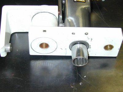
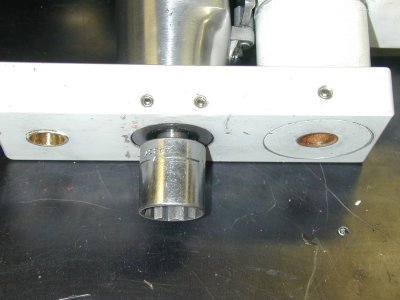
I purchased new drawbar from Enco. 20-1/4"LONG USA DRAW BAR part number 505-2179. I made a bearing bronze collar with the lip to support the drawbar in the center of the spindle. Since the thread on the draw bar is larger then the smooth part, I made the bushing diameter couple thousands larger and threaded. I also made a spacer 1-5/16” long so the bar does not go too deep into the collet should I use double sided end mills. Power drawbar socket now slides nicely onto the ¾” nut. I use 12 point socket as six point binds. I think some old worn out socket work better.</SPAN></SPAN>

I think to make a power drawbar is a nice project as aluminum is cheap and easy on tools. </SPAN></SPAN>

You will be happy with PM1236. I have one for over couple of years and it suits me fine.</SPAN></SPAN>

If one has patience, time and love for machinery it is amazing what can be done with the two machines you own.


Cheers,
Radek</SPAN></SPAN>
 
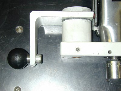
Pneumatic power draw bar in the picture is just another item I could not live without. Seeing all different designs on the Internet, I decided to build my own from the scrap around the shop.

I like your design, just have a couple questions please, 6 or 12 point socket? I'm assuming 6 point but thought you might use 12 for quicker/better alignment, is the black at the end of the socket in the picture just a shadow or is there something there?
My shop is in my basement and anything do do with the compressor scares the ever loving crap out of the cats so I make an effort to keep things as quiet as possible, did you happen to notice if threading the exhaust port would be possible to allow for mounting some sort of muffler? does the exhaust go out the top of the gun in it current orientation.
I've been considering a stacked Belleville Spring design but this is just a much simpler design.

Thanks.:))

If you are not wanting to use air have you considered maybe using the same design/idea with the exception of adding a cordless driver. The only downside there would be the changing and charging of the battery but it may be worth the effort if pneumatic tools are not wanting to be used.

Just a thought.

Mike.
 
have you considered maybe using the same design/idea with the exception of adding a cordless driver.
Mike.

Actually that never crossed my mind but it's a really good idea, I'm going to look into that, Thank you.:))
 
I like your design, just have a couple questions please, 6 or 12 point socket? I'm assuming 6 point but thought you might use 12 for quicker/better alignment, is the black at the end of the socket in the picture just a shadow or is there something there?
My shop is in my basement and anything do do with the compressor scares the ever loving crap out of the cats so I make an effort to keep things as quiet as possible, did you happen to notice if threading the exhaust port would be possible to allow for mounting some sort of muffler? does the exhaust go out the top of the gun in it current orientation.
I've been considering a stacked Belleville Spring design but this is just a much simpler design.

Thanks.:))


I use 12 point socket as 6 point socked binds. Your choice of words is more accurate “quicker/better alignment”.
<O:p></O:p>
The black directly under the socket is just a shadow.
<O:p></O:p>
Yes, I considered some kind muffler, as I try not to use pneumatic tools due to residential area I live in. I can get away with it in daytime hours. I should have this in my main shop where I work on larger projects and it does not matter, but this is my little getaway.
<O:p></O:p>
I am working on it, it is on the list. I do not have a problem with cats, (but the thought brings on a little chuckle), I am dealing with different problem like a domestic dispute. I should not laugh, that is one cute kitty in your picture. The gun is noisy. All the butterfly impact guns (at least the one I came across) the exhaust is under the trigger, for few reasons, Safety of air being dispersed, cleaning of debris under the trigger, so it does not crud the rocker, as the tool is used mostly by body man. Hence redirecting the air will take some thinking.
<O:p></O:p>
I was considering KURT but did not want to part with so much cash, and yes this one is very simple to make. It is not my design as there is dozens of different ones on the Internet. However I took what I thought was the best from them all and incorporate it in my creation.
<O:p></O:p>
If I get more interest on the forum, I can take it all apart and post a few pictures with details and measurements. I did not have any drawing, It was all done from my head., it is very simple. I see Mike zmotosports has some good suggestion. I may add my 2 centavos in when I get back home.
<O:p></O:p>
Sorry for short reply, but I am off to work. I was under the weather for couple of days, hence there was more activity in my postings.
<O:p></O:p>
Cheers,
Radek
 
I do not have a problem with cats, (but the thought brings on a little chuckle), I am dealing with different problem like a domestic dispute. I should not laugh, that is one cute kitty in your picture.

Thank you very much for the reply, the little guy in the picture is my shop buddy, all grown up now, he tries to be helpful by clearing everything off my workbench he doesn't feel I need, he also makes sure I don't twist an ankle by knocking anything on the floor under the hardest to reach places.

Thanks again.:))
 

Here is few more pictures of the draw bar, as I took it apart to install spacers between the individual springs, to eliminate any possible binding. Did not really have a problem, but it was a part of the design.

<O:p</O:p
Here is a link to short little video I made today:
http://www3.telus.net/oceanready/power_drawbar.avi
<O:p</O:p
Cheers to all,
Radek

Power Drawbar 001.jpgPower Drawbar 002.jpgPower Drawbar 003.jpgPower Drawbar 004.jpgPower Drawbar 005.jpg


Power Drawbar 001.jpg Power Drawbar 002.jpg Power Drawbar 003.jpg Power Drawbar 004.jpg Power Drawbar 005.jpg
 
Hi Ratz
If you have drawings of your power draw bar project, I would love to have a copy. For some reason I can't seem to be able to get any of the pictures to show up. Thank you for your time. Rex


Sent from my iPhone using Tapatalk
 
Hi Ratz
If you have drawings of your power draw bar project, I would love to have a copy. For some reason I can't seem to be able to get any of the pictures to show up. Thank you for your time. Rex


Sent from my iPhone using Tapatalk


Hi Rex1954, thanks for your interest.

I do not have a technical drawing, however I am happy to send you dimensions you require. It is somewhat self explanatory from the pictures.

I uploaded the PDF file with all the pictures onto a server so you may be able download the file. Let me know if you are able to get it here.

http://www3.telus.net/oceanready/PowerDrawbar.pdf

You can PM me for specific sizes.

Radek
 
Hi Radek
Thanks for taking the time to post the pics for me. Nice looking setup for sure. I will be in touch via PM to ask some questions..:). Definitely an improvement I want to make. Thanks again for your time. Rex


Sent from my iPhone using Tapatalk
 
Back
Top