Possible motor for mill

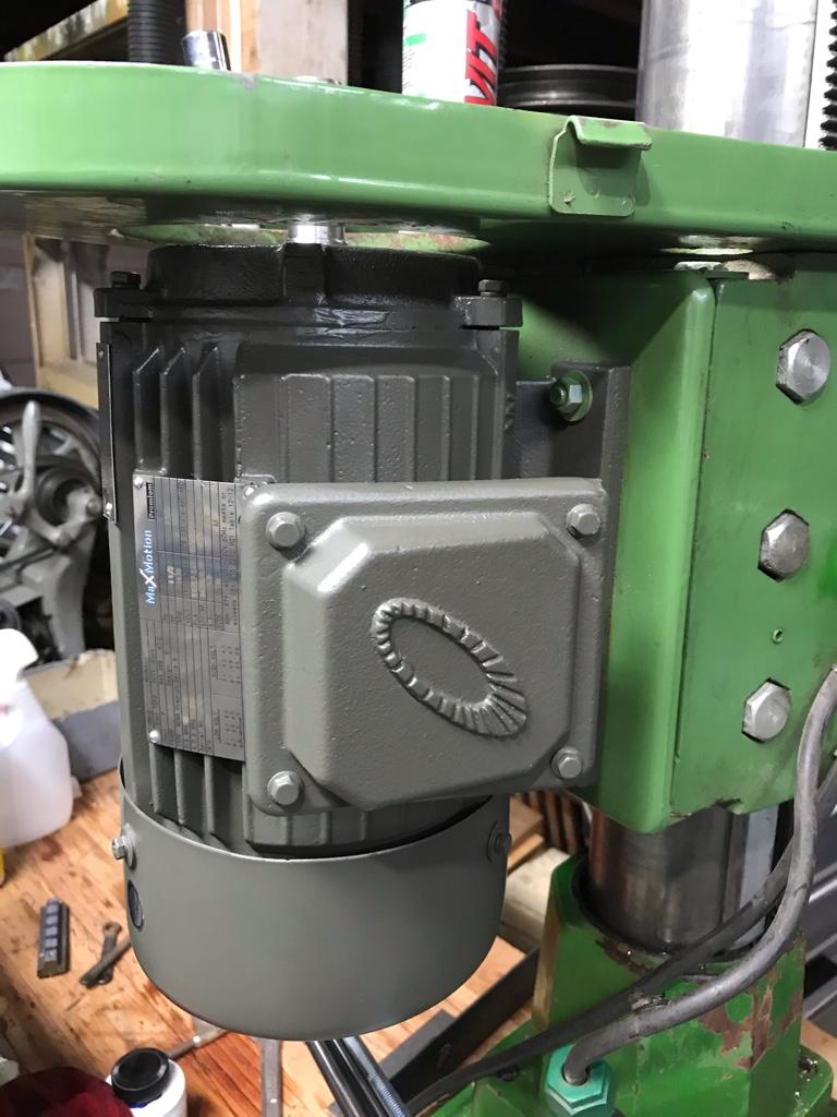
I am running on 240 V.
This is the link to the VFD where I bought the VFD and motor. The specs indicate 230V input.
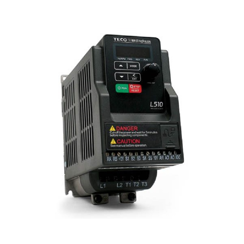

Whoops! My bad, sorry. I was looking on another site and found the "101" model by accident. Read too quickly. Sounds like you have a killer setup.
 
No worries @macardoso!
Ironically I very nearly bought the single phase output version of that unit till I double checked!


Sent from my iPhone using Tapatalk
 
My 3 ph motor arrived today.
1.5 hp 220/440v 3 ph
IMG_6077.jpg

Set to pulling the motor pulley
Don't have a puller so I had to improvise with some all-thread couplers and 3/8" bolts which I used as jacks to lift the pulley off the shaft.
As I got close to getting it off the shaft I ran out of thread on the fully threaded bolts so I ran them back in and put the shouldered bolts in the other end.

IMG_6076.jpg
The pulley was so tight I thought I was going to strip the threads. Even after heating it up with my propane torch it was a struggle to make it budge.

IMG_6074.jpg

Finally got it off. Discovered there was no keyway in the pulley, just a setscrew that seated in the keyway.

I think I'll be shopping for a new pulley as the bore is 15/16" and the new motor shaft is 7/8. I suppose I could bore it out and make a bushing but I have no means to broach the keyway.
 
Last edited:
Fitted up the motor. Used the existing holes in the motor mount. Almost like I planned it that way
d3d9f2cf44168e3d81813a79fad10ea3.jpg


c1c57adad77a55ba4cfc62fbf26f6a3f.jpg


Now all I have to do is deal with this
e6a09404fe36ab1e935ad7ce95d97bb1.jpg


Sent from my iPhone using Tapatalk
 
I had a similar problem removing the motor pulley on my own round column mill when I converted to a three phase motor and VFD. The end of my pulley was closed, because the top sheave had an ID smaller than the motor shaft. I carefully drilled down the centerline (or as close as I could get to it), then tapped the hole for 5/1/16-18 and used a jacking screw (a length of all-thread and double nuts). As I recall, the depth (thickness) of the aluminum was longer than the tap, so I had to partially counterbore 5/16" to get the threads all the way through. You might want to drill and tap your new pulley (or your re-used existing one) in a similar manner.
 
I’m very conservative, I have a single phase to 3 phase VFD conversion on one of my mills. It has the original 5 step pulley system and I change belts and use the VFD in conjunction to obtain the speeds I want. I never go below 30 Hz or go above 60 Hz. The motor is a 2 hp Marathon, according to them, because of the motor age, insulation type, torque requirements and intended use, if I stayed within the 30-60 HZ operating range, the motor should function fine for years. As UD posted, the working parameters of the cooling fan’s operation is extremely important, so far the motor has been going strong for 15+ yrs, without an issue.
 
Last edited:
I had a similar problem removing the motor pulley on my own round column mill when I converted to a three phase motor and VFD. The end of my pulley was closed, because the top sheave had an ID smaller than the motor shaft. I carefully drilled down the centerline (or as close as I could get to it), then tapped the hole for 5/1/16-18 and used a jacking screw (a length of all-thread and double nuts). As I recall, the depth (thickness) of the aluminum was longer than the tap, so I had to partially counterbore 5/16" to get the threads all the way through. You might want to drill and tap your new pulley (or your re-used existing one) in a similar manner.

Thanks that’s a good idea.
In hindsight a puller might have been a challenge because the motor shaft doesn’t extend much past the bottom edge of the bottom sheave meaning the threaded part of the puller would have had to be pretty long.

I’m thinking that I might drill and tap two holes in the top of the pulley. Then get piece of flat bar, drill and tap for 5/16” in the centre with two holes corresponding to the tapped holes in the pulley.
That way I could just bolt the flat bar to the pulley, screw in the 5/16 rod and pop the pulley off.


Sent from my iPhone using Tapatalk
 
I’m very conservative, I have a single phase to 3 phase VFD conversion on one of my mills. It has the original 5 step pulley system and I change belts and use the VFD in conjunction to obtain the speeds I want. I never go below 30 Hz or go above 60 Hz. The motor is a 2 hp Marathon, according to them, because of the motor age, insulation type, torque requirements and intended use, if I stayed within the 30-60 HZ operating range, the motor should function fine for years. As UD posted, the working parameters of the cooling fan’s operation is extremely important, so far the motor has been going strong for 15+ yrs, without an issue.

That sounds like sage advice.
This is an inverter rated motor which the supplier advised is designed to better deal with changes in frequency.


Sent from my iPhone using Tapatalk
 
Thanks that’s a good idea.
In hindsight a puller might have been a challenge because the motor shaft doesn’t extend much past the bottom edge of the bottom sheave meaning the threaded part of the puller would have had to be pretty long.
Welcome! I've always been very hesitant to use a gear puller on an aluminum pulley. It's just too easy to break the aluminum!
I’m thinking that I might drill and tap two holes in the top of the pulley. Then get piece of flat bar, drill and tap for 5/16” in the centre with two holes corresponding to the tapped holes in the pulley.
That way I could just bolt the flat bar to the pulley, screw in the 5/16 rod and pop the pulley off.
I assume your pulley has a through hole. Mine did not. Here's a couple photos of mine, drilled & tapped, along with the jacking screw and the two setscrews (90º apart on the pulley) and the key that secured the pulley to the motor shaft.
kHPIM3802.jpg
kHPIM3803.jpg
 
Spent some time tonight making a bushing to adapt my pulley to the new motor.
Bored out the pulley to 1.125”
Turned down a piece of aluminum to be a slip fit in the pulley bore.
Bored the aluminum to .875” to slip over the motor shaft.
Cut the key way using a 1/8” cutoff blade laid flat in tool holder.
Finished it up with a file.
The bushing turned out pretty good I think. I didn’t bore the pulley deep enough as it’s about 1/4” too high. Easy enough to go a bit deeper.

Bunch of firsts for me tonight , boring, working to a specific dimension and cutting a key way.
fd778268623ed9f9c8631c9733f8f7e8.jpg


6d95f425cf705a4b8fe8d207c324049e.jpg


8a993ee64bf206c174dc75b2efa4ca97.jpg


88a50f06a3964ad074b5cc3a6977563b.jpg


Sent from my iPhone using Tapatalk
 
Back
Top