POTD was FINALLY getting my Delta 12” miter saw laser lines repaired (correctly). This saw has a couple of line-lasers that scrub the sides of the blade to show where the blade will cut.
First the backstory from this summer. The transformer had failed, I replaced it with an LED driver or whatever it was called; was supposed to put out around 5V. I wired it in place, flipped it on and toasted the two lasers. I checked the output of the driver with a voltmeter and read something like 30V. Turns out that the driver puts out a constant current, not voltage. An LED driver IS NOT the same thing as a transformer.
Amazon to the rescue with a couple of line lasers for under $10 and a 5V transformer. The next problem was the mounting brackets for the saw’s lasers expect a 10 mm diameter laser, and I could only find 9 mm. Back to Amazon again for some 10 mm OD, 9 mm ID brass tubing. The tubing was cut to make a couple of bushings which were epoxied into the saw’s plastic laser brackets. Then pressed the lasers into the bushings, did some alignment adjustments, and life was good again, until it wasn't.
I couldn’t figure out why at the time, but the left-side laser would continually move out of alignment. I had done the same repairs to both sides; RH side was okay so obviously I’d screwed something up on the LH side. Figuring out what was wrong finally bubbled up to the top of my “list of good intentions”. I pulled the laser and laser mounting bracket to figure out what I’d done wrong. Well, in the process of pulling the laser, I pulled the wires out of the unit. Back to Amazon for another pair.
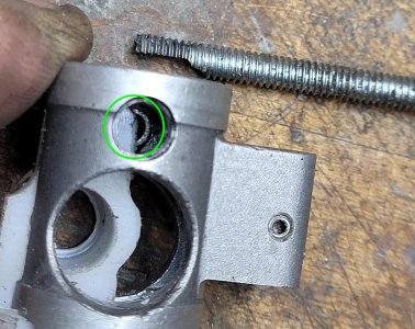
The saw’s laser presses into a plastic bracket, which in turn presses into an aluminum bracket that mounts to the saw. When I made the brass bushing, I’d made it a little too long so the plastic bracket wouldn’t slide out of the aluminum one. Trimmed a little brass off the top and got the plastic piece out. Next step was trying to peel out the brass bushing for a replacement, then this happened.
Doh! Snapped the plastic detail that holds the LH side line laser
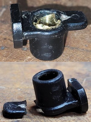
FINALLY, Bruce is getting to the POTD, making a new plastic detail to hold the laser in the miter saw! I’d checked before online for a replacement part which was around $200+.
On the plus side of making a new part, I “probably” figured out what I’d messed up. The laser needs to be aligned so its line is parallel to the plane of the saw blade. That’s done with a hex feature on the laser which makes for easy “clocking” adjustments until it’s parallel with the blade. I do this by making a cut with a clamped-down board, then clock the laser until it’s parallel to the cut. I’ve also done it by setting a piece of paper up against the blade when it’s down, then raise the saw and clock the laser to the edge of the paper.
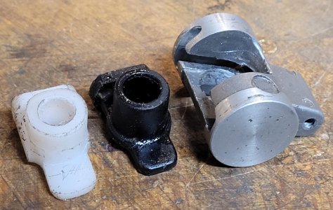
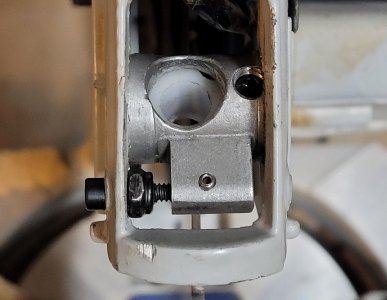
The plastic bracket that holds the laser slips into an aluminum bracket that mounts to the saw. The aluminum bracket has a compression spring that bears on the bottom of a tab on the plastic bracket, and a set screw above which pushes down on the bracket. The set screw and spring set the plane of the laser as the saw is raised/lowered. This one is pretty easy to adjust also. Raise the saw, line up the edge of a piece of paper with the laser line, then lower the saw. If the plane is correct, the line should stay on the edge of the paper. If it moves to either side of the edge, the set screw is tightened/loosened to adjust the plane. I think this is where I initially screwed up when the laser was replaced. I think when I slid the plastic bracket into the aluminum one, I didn’t get the spring under the plastic bracket. The laser line would move 1/8” either when I powered up the saw and/or when I tapped on the laser area.
There are three adjustments to align the laser. I align by first adjusting the set screw which angles the laser so it's projecting parallel to the plane of the blade (A-datum, set the plane). There's a little clearance between the plastic bracket and the aluminum bracket on the left hand side looking at the picture below. That allows the set screw and spring to "springboard" the plastic bracket and change the aim plane of the laser. The horizontal "T" on the right fits tightly in the aluminum bracket while the rest is loose. Then rotate the laser itself so its line is parallel to the blade (done with the hex on top of the laser or B-datum, set the line). Lastly, adjust the laser bracket side to side until the laser line is "scraping" the edge of the blade (C-datum, move on the line to set a point). It's easy to spot as the laser line starts to get dimmer as it silhouettes on the blade.
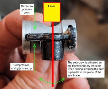
The replacement plastic bracket was made from Delrin; material on hand. My plan was to hold the part after the initial drilling of a clearance hole with 5-C collets for lathe and mill work. The extra work holding material would be machined or sanded away.
I started by turning the 1.5” Delrin OD down to ¾” so it’d fit into a collet. Drilled an undersized through clearance hole, parted, flipped it over, and turned the diameter down so it’d fit in a 5-C collet. Then bored the hole to depth for the 9.0 mm diameter laser. The through hole in the part has a smaller diameter opening at the bottom so the laser can’t be pushed in too far (and hit the saw blade).
Turn the 1.5" Delrin to a shoulder for grabbing with a 5-C collet, drill an undersized through hole and part
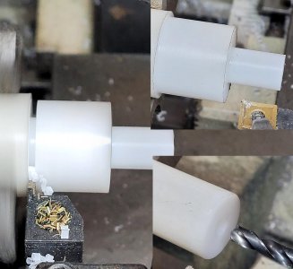
Move from the Grizzly lathe to the Clausing with a 5-C collet chuck. Turn a shoulder for subsequent 5-C collet holding, bore a 9mm hole to proper depth (note the 2" travel indicator for Z-axis depth). Test fit the laser in the 9mm hole.
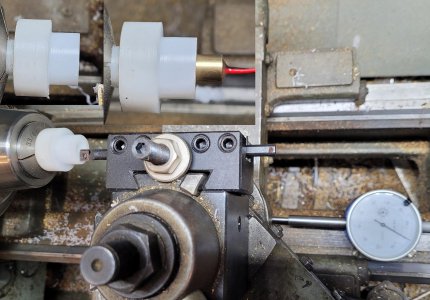
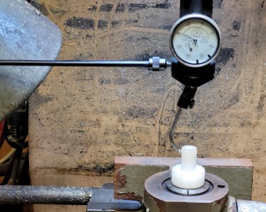
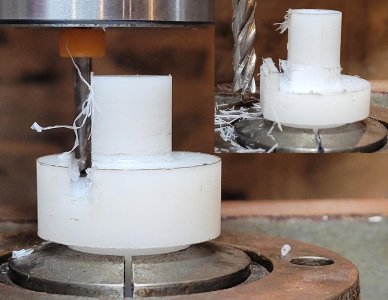
Went to the Bridgeport with a 5-C collet holder and found the center with a Blake Co-ax. Then it was whittle away with an 1/8” and ¼” end mill. It dawned on me at this point that a smarter person would have made both ends of the bracket the same diameter. DUH! I have to flip the part on the BP to do work on both ends. One of the cylindrical ends would be totally removed (it was there just to provide something to clamp onto), so its diameter didn’t matter. For whatever reason I’d made either end a different diameter which would drive a collet change when the part was flipped on the BP.
Finding center of the part with a Blake Co-Ax
Whittling away at the top side
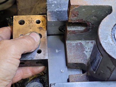
The collet holder's tightening nut is on the bottom of the holder. So, it would need to be removed to change collets. Again, a smarter person would have lined up the edge of the collet holder with the edge of the vise for easy realignment when it was set back in the vise. Of course, if I’d have turned both ends of the part to the same diameter, all of this would have been avoided. I used an adjustable parallel on the side of the collet holder and spread it until it hit a 1-2-3 block. Plan was to pull the collet holder, change collets, then set the holder back in the vise using the 1-2-3 block and adjustable parallel to get the holder back in the same position. Or, I could have set it back in and realigned with the Blake again.
Doh! I turned the 5-C shoulders on either side of the part to different diameters (poor planning on my part). Not a huge deal, other than my 5-C collet holder loose tightens the collets from the (not accessible) bottom side. On top of that, I should have aligned the collet holder with the edge of the vise jaws for easier realignment if it needed to be removed. Work around was setting an adjustable parallel to fill the gap between a 1-2-3 block on the edge of the vise jaw and the collet holder.
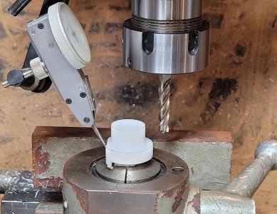
Flipped the part, and realigned it rotationally by sweeping a previously machined flat face. Then finished the end mill whittling on the opposite side (plus a little bench filing and box knife work).
Swept the previously machined surface to "clock" the part into alignment, then tighten the cam lock.
Whittled away at the opposite side to roughly mimic the original plastic bracket.
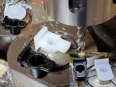
Finished part
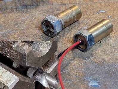
The original line laser had a hex feature on the back for clocking the laser for alignment parallel to the blade. I chucked up a ¼”-20 nut and drilled it out to 9 mm. Pressed on the laser with a dab of Loctite. Oh, I also put a dab of 5-minute epoxy on the back of the laser where the wires come out to better reinforce them.
Drilling out a 1/4"-20 nut with a 9mm drill to add a hex feature on the back of the laser. I typically align nuts in the 3-jaw by running a couple of them on a bolt spaced 1" apart, then tighten the assembly in the jaws and back off the bolt. It helps get the nut center hole in line with the lathe's axis (nut isn't tipped for off-axis drilling)
I used an 8-32 screw with part of the end ground off to shove the compression spring down while inserting the plastic laser holder. Didn’t want a repeat of my first laser replacement screw up.
Pressing down on the compression spring to make sure it's under the tab on the plastic bracket.
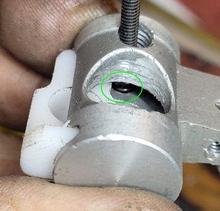
Got in under the plastic bracket, ready to fully seat the bracket
Aluminum and plastic laser brackets in place. The screw on the left adjusts the aluminum bracket back & forth to adjust the laser line so it's just "scrubbing" the side of the blade.
All good!
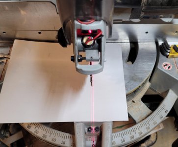
And so far, so good. Two weeks later and it’s still holding alignment though with my original “fix” I’d see the line move just by pulling on the motor start switch. I’m confident in the fix at this point.
Thanks for looking, Bruce
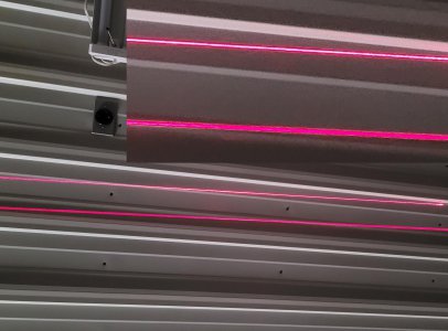
Not to belabor it (but too late. . . ) there are multiple versions of these line lasers out there. I currently have the one on the bottom in the RH laser and the upper as the LH laser. The jury is still out for which style I'll go with on both sides. I like the thin, crisp line of the top one, but it's a little tough to see under my bright shop lights. The lasers are around $7 a pair and a 5 minute job to swap. I'll probably let my wife (who uses this saw a lot) make the final call.

 www.hobby-machinist.com


