Powering A Grinding Spindle With A DC Motor.

I'm guessing you can't just pull the controller off of the mill the motor came off of? The easiest thing to do would be to find a replacement driver for that motor. I am guessing it would be cheaper than a VFD in any case.

I do have the original Controller, but that's the thing I'm not sure what went wrong, Novakon wanted to charge me $100 plus the shipping to check it out, after the outstanding service I had received up until that point I past on the offer, died on the 4th piece, wonderful...!
Please excuse my terminology if it's off electronics just doesn't stick in my head, I looked around at what others had done and decided to invest the ($100 plus shipping) into a replacement motor, 3 phase and the board with a VFD.

Thank you for the advice, I'll check into this.

Don
 
Hi Don,

While I am not real "Hi-Speed" on motors, I don't think a VFD will work with your motor. The "Hall" wires are for a sensor which is used by the controller to determine the motor speed. They would not be used on a conventional VFD.

Many have had good luck replacing their stock DC controllers on their small mills with ones from KB Electronics. They are reasonably priced and their website has some good info:

http://www.kbelectronics.com/Variable_Speed_DC_Drives.html

Bob


Bob, you are partly correct. The Hall sensors are for very precise speed control on VFDs and servo drives that have the provision for that input. They are also used for positioning in a closed loop servo system in CNC and other applications that require positioning accuracy.

In this application a variable output frequency from the VFD is all that is required to operate the motor as a standard 3 phase, the Hall wiring would not be used at all. To the VFD, this motor would look like any standard 3 phase motor.

This motor is not a DC motor, so a DC speed controller would not work.

A BLDC motor is actually a 3 phase motor constructed with a permanent magnet armature so that they have the capability of producing near 100% torque at near 0 RPM and have a nearly flat torque curve over their speed range.
 
Hi Don,

While I am not real "Hi-Speed" on motors, I don't think a VFD will work with your motor. The "Hall" wires are for a sensor which is used by the controller to determine the motor speed. They would not be used on a conventional VFD.

Many have had good luck replacing their stock DC controllers on their small mills with ones from KB Electronics. They are reasonably priced and their website has some good info:

http://www.kbelectronics.com/Variable_Speed_DC_Drives.html

Bob

Thank you Bob, I'll look into this, I guess I have some reading to do..!:))

- - - Updated - - -

A BLDC motor is actually a 3 phase motor constructed with a permanent magnet armature so that they have the capability of producing near 100% torque at near 0 RPM and have a nearly flat torque curve over their speed range.

Jim, thank you so much you have been so helpful.:))
 
Bob, you are partly correct. The Hall sensors are for very precise speed control on VFDs and servo drives that have the provision for that input. They are also used for positioning in a closed loop servo system in CNC and other applications that require positioning accuracy.

In this application a variable output frequency from the VFD is all that is required to operate the motor as a standard 3 phase, the Hall wiring would not be used at all. To the VFD, this motor would look like any standard 3 phase motor.

This motor is not a DC motor, so a DC speed controller would not work.

A BLDC motor is actually a 3 phase motor constructed with a permanent magnet armature so that they have the capability of producing near 100% torque at near 0 RPM and have a nearly flat torque curve over their speed range.

Hi Jim,

Thanks for the info, although now I am confused, which is not unusual! I see that the link I posted does not apply to that specific motor as they are not BLDC drives, OOPS. So here is my question. After some reading, BLDC motors require some type of closed loop feedback, either hall effect sensors or back-emf. How would a VFD drive a BLDC motor? Does it sense the back-emf for proper commutation?

Thanks for your help,
Bob

- - - Updated - - -

Thank you Bob, I'll look into this, I guess I have some reading to do..!:))

- - - Updated - - -


Jim, thank you so much you have been so helpful.:))

Don,

Jim was kind enough to straighten me out on the motor driver. Please disregard the link I posted as those drives not apply to your motor. Sorry about that.

Bob
 
Hi Jim,

Thanks for the info, although now I am confused, which is not unusual! I see that the link I posted does not apply to that specific motor as they are not BLDC drives, OOPS. So here is my question. After some reading, BLDC motors require some type of closed loop feedback, either hall effect sensors or back-emf. How would a VFD drive a BLDC motor? Does it sense the back-emf for proper commutation?

Thanks for your help,
Bob


Bob, again you are partly correct. The feedback loop is required for speed control if the controller does not output a set frequency via a phase locked loop internal in the controller. There are VFDs with what is called Sensorless Vector Control, those do sense the back EMF for commutation.

It really depends on the application that the motor will be used in. Normally you would never use a BLDC motor in an application where a standard motor would do just because of the cost difference (like running a grinder), but if you have one laying around.... A BLDC motor would be happy running off of the 60Hz, 3 phase line without any control system ahead of the motor. (assuming the voltage was correct).

We normally think of 3 phase motors as being something you would find in an industrial environment, running heavy machinery. This is not so much the case today. BLDC motors are everywhere, from model RC cars and aircraft and small battery power tools, to heavy industrial machinery. Most of the new battery drills have BLDC motors in them and the feedback loop is via the trigger.

I hope this makes sense.

Thanks Jim. It's starting to make more sense, but now I really have a lot of questions! Maybe I'll start a new post. At the risk of hijacking this thread, I would like to ask one more.

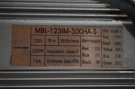
I have an Optimum BF30 mill and the motor has significant cogging. The manufacturers tech has told me he believes their motor driver is sub par. Do you think I could connect my 2HP Teco VFD to the mill motor and see if it runs better? I would run the motor under no load as it is rated at 3HP, 2200W. Below are the specs.

BF30 Motor Nameplate.jpg


Thanks for your help.

Bob

BF30 Motor Nameplate.jpg
 
Thanks Jim. It's starting to make more sense, but now I really have a lot of questions! Maybe I'll start a new post. At the risk of hijacking this thread, I would like to ask one more.

I have an Optimum BF30 mill and the motor has significant cogging. The manufacturers tech has told me he believes their motor driver is sub par. Do you think I could connect my 2HP Teco VFD to the mill motor and see if it runs better? I would run the motor under no load as it is rated at 3HP, 2200W. Below are the specs.


Thanks for your help.

Bob

It should work OK for testing. I would start at maybe 15% speed and dial it up slowly while watching the amps on the display, don't let it go much over the max rated amps for the VFD. VFDs will generally take about 115% of max amps without complaining too much. I don't know how to display the amps on that unit, but normally you just push the up or down programming arrows to change what parameter is displayed while running. Then turn the speed down again before hitting the stop button.

The VFD will limit the output current to keep it's self from self destructing.

Excellent, thank-you Jim. I'll give it a try.

Bob
 
Excellent, thank-you Jim. I'll give it a try.

Bob

Please let me know how that works out. I expect that you may get some cogging at low RPM, but is should smooth out as the speed comes up a bit.
 
Thanks Jim. It's starting to make more sense, but now I really have a lot of questions! Maybe I'll start a new post. At the risk of hijacking this thread, I would like to ask one more.

I have an Optimum BF30 mill and the motor has significant cogging. The manufacturers tech has told me he believes their motor driver is sub par. Do you think I could connect my 2HP Teco VFD to the mill motor and see if it runs better? I would run the motor under no load as it is rated at 3HP, 2200W. Below are the specs.

Bob

Hi Bob, no worries about the thread the question suits the spirit of it, and it's interesting, could you please tell me what you mean by "cogging"
When I looked it up it said "Cogging means that when you turn the motor by hand it jumps from one magnet pole to the next and feels bumpy when you turn it" but I'm thinking you might mean something about how it running.
 
Back
Top