Hello everyone.
I've been searching for a solution to my wiring problem for days and the longer I search the more confused I get. I'm electrically challenged and flunked out of Electrical Engineering 101 in college. I enjoyed building Heathkit projects but that only required soldering skills, no theory.
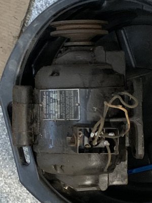
My problem is: I recently purchased a 1946 Logan lathe with original motor and drum switch. This, I understand, predates some electrical labeling standards so wire labels may be non-standard.
I think the lathe lived in a school for part of its life because half of its gears are missing teeth and the wiring is held together with great amounts of electrical tape.
The motor is a Peerless 1/2 HP, 1750 RPM, Single Phase, Dual Voltage. It is reversible.
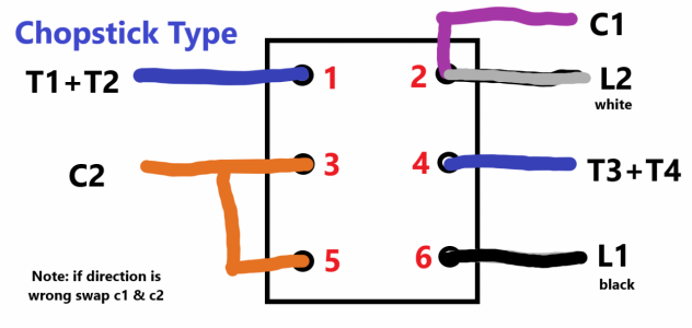
There are 6 leads coming out of the motor: T1, T2, T3, T4, C1 and C2. Here is a picture of a different but similar motor showing a wiring diagram:
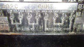
And this matches all of my research on my motor.
So, if I combine T1+T2 and T3+T4 at the motor, there will be 4 motor wires at the drum switch: T12, T34, C1 and C2.
The drum switch is:
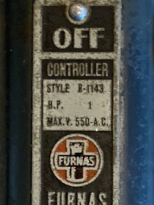
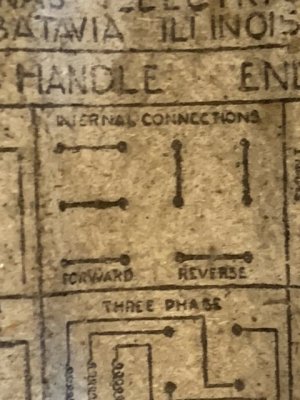
I'm hoping that there is a simple, single best practice solution to this?
Thanks everyone in advance and I apologize for being electrically challenged!
Rob
I've been searching for a solution to my wiring problem for days and the longer I search the more confused I get. I'm electrically challenged and flunked out of Electrical Engineering 101 in college. I enjoyed building Heathkit projects but that only required soldering skills, no theory.
My problem is: I recently purchased a 1946 Logan lathe with original motor and drum switch. This, I understand, predates some electrical labeling standards so wire labels may be non-standard.
I think the lathe lived in a school for part of its life because half of its gears are missing teeth and the wiring is held together with great amounts of electrical tape.
The motor is a Peerless 1/2 HP, 1750 RPM, Single Phase, Dual Voltage. It is reversible.
There are 6 leads coming out of the motor: T1, T2, T3, T4, C1 and C2. Here is a picture of a different but similar motor showing a wiring diagram:

And this matches all of my research on my motor.
So, if I combine T1+T2 and T3+T4 at the motor, there will be 4 motor wires at the drum switch: T12, T34, C1 and C2.
The drum switch is:


I'm hoping that there is a simple, single best practice solution to this?
Thanks everyone in advance and I apologize for being electrically challenged!
Rob


