- Joined
- Jun 12, 2014
- Messages
- 4,827
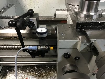
Using the right proximity stop is part of the puzzle, it is a trade off of high refresh rate, sensing range and it needs to be shielded. The unshielded I would expect to be less reproducible vs. shielded. Since I embed my sensors, I can only use the shielded types. I use triple sensing shielded sensors typically with refresh rates in the 500 Hz or higher and sensing distances between 12-20 mm depending on the model and if it is a 18 mm or 30 mm body. The one below has been very consistent and you should be in the +/-0.001" repeat range for a a 12 TPI or higher, but as you increase the speed it might vary to +/-0.002 at 500-600 RPM. I use a 30 mm sensor on my lathe, I would figure I could thread on upwards of 1000 RPM, but see no need when I get very clean threading at 300-600 RPM.
Other factors are the type of VFD being used and also the programming parameters, as mentioned too quick a stopping time will decrease accuracy if the VFD is trying to prevent an over voltage buss error. On the Yaskawa drives I disable this parameter, but also make sure that I do not use too short a stopping time. On heavier machines I may use DC injection for stopping the last couple of Hz, but it all depends on the lathe/system and requires some parameter tuning.
Another thing to think about is rotating mass and momentum, if the mechanical top speed is set lower say 200 RPM at 100% speed there will be more mass spinning for the same RPM vs. having the gearing set for 800 RPM and the speed pot is turned down to 25%. Similar to a mill or lathe in back or low gear vs. normal/high gear, the former takes longer and is harder to stop. Using an encoder might give tighter control, but at the end of the day there is a limit to how much energy the VFD can dissipate when braking.
I also recommend using an additional small limit switch in series with the sensor as a backup to the proximity sensor should it fail or one drives the carriage in the wrong direction. Last but not least, I have been adding chip shields over my sensors, as a stray chip or swarf will instantly trigger the sensor.


