Reversing a single phase 120 V motor

Just make certain that the switch comes with a cover like 'Hman' posted (in post #9) or that you make some sort of cover so that you do not (and can NOT) accidentally bump the switch in the opposite direction while motor is in operation. I'm certain you know this but it's worth saying, make certain toggle sits in center position until motor has come to a complete stop. I accidentally fried my board on a piece of equipment because I didn't have a cover, brushed the switch and inadverntently flipped it. It created an emotional event :guilty: $$
 
Those covers are made to keep the switch in off, on a two throw (on/off), or one of the ends in a 3 throw switch(on/off/on). I have never seen on that will lockout one throw of a 3 throw switch.

You can easily make a block, using a spring loaded hinge, with one side cut, and bent so that it will block the one end movement.\, and needs to be pulled out of the way to use that position of the switch.
 
Superburban, well there are tons of them out there, without covers, that's why I posted what I did.
290412 290413 290414
 
Last edited:
Old geezer throwing his 2 cents worth in, yet again. This issue has been covered many times in the past, just look into older posts. It seems to have been covered here, as well. Although a little spotty, with so many contributors holding forth. I am (was) a commercial/industrial electrician. This job is always just a few minutes of studying the motor and then hooking it up. You've already studied the motor, so... ... ...
First issue, single phase motors are NEVER instantly reversing. Plugging only works on 3 phase and DC motors. If you flip the reversing switch when it's running, nothing happens. It keeps running, usually to the detriment of whatever work is being done. There must be an ON/OFF switch, usually separate. There are exceptions to these, as any, rules. But, all in all, rare.
Many(most) folks end up with a drum switch, which serves both purposes. Although they may not have started with one. Looking into the "innards" of a drum switch, you will find a pair of contacts that operate in both directions. And four others that make up a reversing switch. I won't go any further on that subject because there are many different designs.
To answer your original question, you will need 2 switches. Assuming that most of your work will be uni-directional, the ON/OFF switch is the more subject to wear. On my Atlas miller for example, I had the front panel switch for ON/OFF. The reversing switch was hanging on a pigtail that dropped from the motor. It was eventually rewired with a drum switch, once I settled on a standard. In your case, where to hang the switch will be your call. Just make it a determined movement to operate.
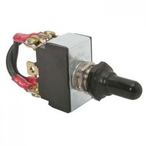
There are several switches that are for that purpose, mostly costly. Just a DPDT switch works well enough. Wire the two red wires to the center two lugs. Wire the two motor stabs to the two lugs on one end. Then take the other two lugs and cross them and connect to the first end. Most any switch will do the job. Just look for the six lugs on the back. Go for the higher current switch, if available. The post prior has a very good photo of the switchs. The one on the left.
I must apologize, I'm still recovering from a computer crash. I have the drawing, just not sure where it resides right now. A couple of months back, I was prowling on eBay. There was a listing for a motor switch, a drum switch, for about $12US. Plastic, but well made. No flexing. I bought a half dozen, some to "standardize" my machines, some for standby parts. Not much more than a good toggle switch will cost. Just a longer delivery time. Worth looking for... ... ... BTW, WinDoze 10 sux, big time... ... ...
Bill Hudson​
 
First issue, single phase motors are NEVER instantly reversing. Plugging only works on 3 phase and DC motors. If you flip the reversing switch when it's running, nothing happens. It keeps running, usually to the detriment of whatever work is being done. There must be an ON/OFF switch, usually separate. There are exceptions to these, as any, rules. But, all in all, rare.

Bill Hudson​
Thankyou Bill. I thought that was the case, but not positive. Now I know. Will it hurt the single phase motor? my understanding is the run windings are the same for either direction, it is the start windings that work differently for each direction. So fliping the switch while the motor is above the speed where the start winding switch kicks out, will do nothing.
 
Operating the reversing switch while the motor is running, in most cases, will do nothing because the "start winding" is run through a centrifugal switch that opens at around 50% speed. But will cause a definatly unsettling experience the next time power is cycled. Basically the motor runs on one winding once up to speed. There are exceptions, sure. But the way you described the motor, it sounds like the theory fits.
It won't damage the motor in most cases, unless something out of the ordinary happens. Like when it doesn't start "right now", the magic smoke will get out. As long as it comes up to speed in a second or two, you're good to go. When you question whether or not there is something wrong with the motor, remove the load(belt) and run it. If it runs well enough there, then start looking. If it hums, or rattles, or shakes, and doesn't come up to speed right away, look at the capacitor first. Then the start switch. The cap is easier to get to, and the most likely to fail. Keep an extra on hand and swap it out at the first sign of trouble. The centrifugal switch is inside, and very difficult to get back together right.
 
Hudson, thank you for highlighting that a motor's centrifugal switch is out of operation when a motor is at full speed.

For others that follow, a motor's internal centrifugal starting switch, does become engaged again (drop back in) when the motor begins to slow down. This does occur with most motors while motor shaft is still spinning from it's prior operation. With some motors that's almost at creep revolution. But, none-the-less, the centrifugal switch does drop back in and become 'engaged' again while motor's rotor (shaft) is still in motion. You can hear the switch on most motors if you listen closely.....sounds like a clicking sound coupled with a thud.

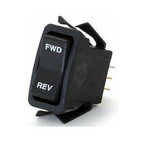
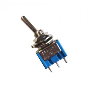
For what it's worth and for clarity sake on my part...of the switches that I posted in #13, the two on the right are more than likely not rated for the amperage capacity of most motors on most of our machines. Some smaller benchtop machines, using small dc motors, they may be fine. I had posted those three photos, by just arbitrarily grabbing some offline, as a measure to reveal there are double pole, double throw switches which don't possess safety covers. I didn't however, consider them being interpreted as a suggestion of a grade of switch to be used in this situation. That is my fault, I should've put more thought into my post I suppose. :distrust:

However, as Hudson highlighted, the one of the left could more than likely be used for a situation similar to the original post. It has beefier contacts and spades, which appear to be of a rating to handle a 1/2-3/4 horse single phase motor. Most of that particular style are rated upwards of 15-20 amps.

I apologize for taking the thread into skewfield for a moment. :chagrin:

(changing gears) The start windings are no different than run windings in the way they see electricity. Apart from the fact, which we will not get into, their make/turns and wire size are different for the start winding. But they don't "work differently than run windings". They're just a winding just as the running winding is. It's just that when we switch the hot and nuetral wires 'ahead of' the start capacitor, which is what we are doing with the double pole-double throw switch, that we reverse the path of the power feeding through -capacitor to start winding- so that it's now flowing through -start winding to capacitor-. And its that momentary current lead or lag associated with this arrangement which allows either the start winding or run winding to build up it's magnetic field before the other.
 
Last edited:
I'm not sure where it came from, but a response showed up in my eMail inbox. Maybe I'm just not up to speed yet on this new WinDoze 10 stuff. When I answered, it bounced.
The biggest reason I pointed out the switch from the post was that it indicated the crossed wires clearly for a reversing switch. I have used that contact arrangement for many a year with my model trains. Going back to the 60's... ...
Once I came off of ships in the early 70's and went to work in the mills, it was instinctive. The drum switch I mentioned is at:
https://www.ebay.com/itm/60-A-Drum-...877932?hash=item5b5075232c:g:UxwAAOSwfQtbUAmo
The price hasn't changed much, a few cents higher. They include a diagram in their posting. But it shows only which terminal to connect to, not what the contacts actually do.
I am pleased with the heavy plastic used. Not flexible in the slightest. At 60 Amps, it should stand up for a long time on fractional HP motors like I use.
BTW, my Atlas mill must be reversed because in addition to the arbor mounted cutters, I use single ended end mills. Reversing the motor prevents "climb" milling that way.

Bill Hudson
 
As a matter of isolation, you never want to break out 120V lines to a switch appliance, especially a metal bat handle type switch. I see it done all the time, and although expedient, it is not cool. The preferred means is using a relay with the switch powering a low voltage relay coil.
 
As a matter of isolation, you never want to break out 120V lines to a switch appliance, especially a metal bat handle type switch. I see it done all the time, and although expedient, it is not cool. The preferred means is using a relay with the switch powering a low voltage relay coil.
Just to clear up the waters for any future readers-- it's perfectly ok to use 120 volts at drum switches. I wouldn't say "never". There are more than one ways to wire up projects and some ways could be argued to be safer than others. However, modern drum switches are almost always rated up to 600VAC and possess contacts which are not only engineered to carry motor loads but manufactured to do so. As far as concerns regarding shock hazards, this is what the green bonding screws are for inside the device-- for grounding the metallic housing to prevent electric shocks.
 
Back
Top