

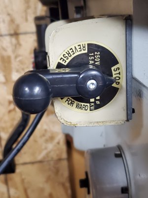
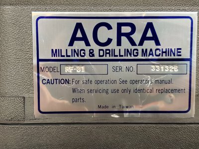
I bought this mill recently and I've ran into some problems. PLEASE SKIP THE BACK STORY & PROCEED TO ADDENDUM BELOW IF YOU JUST WANT THE SPECIFIC CONCERN.Back story-the seller said this was wired to 120v. I got it set up at home(120v outlet) and started milling. I was using the 3rd fastest spindle speed belt set up.(around 1500 rpm) A couple hours into my project I heard a pop. unbeknownst to me my motor was REALLY hot and yep you guessed it I blew the motor start capacitor. I replaced the cap and started milling again,this time watching the motor temp. and in just a few minutes the motor felt like it was heating up again. Also I just noticed the motor wont start under the load of the two fastest belt configurations, (around 2000 and 2500 rpm. I just hums and pops the reset button. I tried giving it a boost by spinning the belt by hand to no avail. This launched an immediate investigation into the power supply in my garage. I know there's a chance the problem may lie in the motor but I have a gut feeling the 120v line from the main to my garage is under powered due to tweakers lived here before me and they weren't shy about messing with stuff. Just looks shotty. I been looking for a reason to run 240v outlet to my garage anyways. So it got dark before I finished the 240v outlet project, I need daylight to finish. So I decided to turn my attention to wiring the mill from 120v to 240v. I popped the cover on the motor and the wiring doesn't match either schematic 120v or 240v???Also when I took the motor to match up the capacitor the guy at the electric motor shop said that the wiring didn't look right,but at that time I was still under the impression the mill was running fine on 120v and it was just a bad capacitor. I told him that's how I got it and it seemed to work before the cap blew so he left it as is. what say ye? Is this wired wrong??? Should I move the wires to match the schematic for 240v or am I missing something regarding the schematic? Also do I need to change the wiring on the forward/reverse switch when moving over to 240v or is the forward/reverse switch wired the same for 120v and 240v? I'll attach pics of the mill,motor,plug it came with, motor wiring,motor cover schematic, switch and switch wiring. ADDENDUM -
Sorry about the biography. let me try to be more specific. I will list things from the perspective of if you standing next to the mill
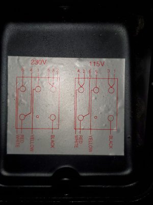
looking at it straight forward just like the picture view I posted.In the diagram its listed as follows
240v:
top left post - 3,5,2 / top right post - black
middle left post - 1,yellow / middle right post - nothing
bottom left post- 6,white / bottom right post - 4,red
120v:
top left post - 3,1 / top right post - black
middle left post - 5,yellow / middle right post - nothing
bottom left post - 4,2,white / bottom right post - 6,red
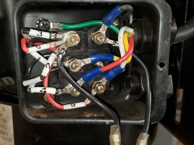
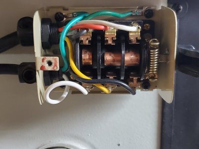
its currently wired as follows on my machine and the picture i posted
top left post - 3,5,2 / top right post - black
middle left post - 1,yellow / middle right post - nothing
bottom left post - 4,red / bottom right post - 6,white
and the thermal reset button is the two blacks connected to the top left & top right posts
my concern is the motor wiring follows the schematic for 240v except the bottom left post & bottom right posts which are reversed
compared to what the diagram shows. again I apologize if i'm missing something or seeing it different than everyone. I will just leave it as is if you guys think its correct. im almost done with the new 240v line to my garage.

Sorry about the biography. let me try to be more specific. I will list things from the perspective of if you standing next to the mill
looking at it straight forward just like the picture view I posted.In the diagram its listed as follows
240v:
top left post - 3,5,2 / top right post - black
middle left post - 1,yellow / middle right post - nothing
bottom left post- 6,white / bottom right post - 4,red
120v:
top left post - 3,1 / top right post - black
middle left post - 5,yellow / middle right post - nothing
bottom left post - 4,2,white / bottom right post - 6,red
its currently wired as follows on my machine and the picture i posted
top left post - 3,5,2 / top right post - black
middle left post - 1,yellow / middle right post - nothing
bottom left post - 4,red / bottom right post - 6,white
and the thermal reset button is the two blacks connected to the top left & top right posts
my concern is the motor wiring follows the schematic for 240v except the bottom left post & bottom right posts which are reversed
compared to what the diagram shows. again I apologize if i'm missing something or seeing it different than everyone. I will just leave it as is if you guys think its correct. im almost done with the new 240v line to my garage.
Attachments
Last edited: