
Also just wanted to throw it out there I am not disregarding anyone's advice . The last post was just to say where its at right now. If its not right Im open to change things around immediately. Its very evident electrical is a weak point for me but I'm eager to learn. Just wanted to say that.

-
Welcome back Guest! Did you know you can mentor other members here at H-M? If not, please check out our Relaunch of Hobby Machinist Mentoring Program!
You are using an out of date browser. It may not display this or other websites correctly.
You should upgrade or use an alternative browser.
You should upgrade or use an alternative browser.
RF-31 I think my motor is wired incorrectly,take a look plz
- Thread starter zdiaz925
- Start date
- Joined
- Oct 10, 2018
- Messages
- 543
People do some shocking things with wiring at times. (See what I did there?I am baffled as to why there was a 120v plug setup yet wired for 240v and he said he had been running on 120v
") )
)The PO _may_ have taken an existing 120V circuit (hot/neutral) and changed it to 240V (hot/hot). And continued to use the 120V-style receptacle outlet and plug. Of course, that is stupid and dangerous...but it happens. Worse, he may have forgotten that he did it.
BTW, does anybody know what would happen if a typical (120V) circuit tester is plugged into such a circuit? Does the magic smoke pour out?
Craig
- Joined
- Apr 30, 2015
- Messages
- 11,320
I see what you mean about the differences, not a big deal, it gives the same result even though the colors are swapped
Also, the breaker connection really is wrong if you still have it connected between black and 2,3,5- I'm at a loss to explain why it's working. I suspect the breaker is actually broken (open circuit) so removing it should have no effect.
-Mark
Also, the breaker connection really is wrong if you still have it connected between black and 2,3,5- I'm at a loss to explain why it's working. I suspect the breaker is actually broken (open circuit) so removing it should have no effect.
-Mark
Last edited:
I don't think it was working lol. The issue that started this adventure down the rong-fu rabbit hole began with the motor over heating until my starting capaciter exploded. So using the wiring diagram(red writing on back off cover)on my mill does that reset button still install the same way as in the black and white schematic.between #4 and black?I'm at a loss to explain why it's working.
where would the little breaker go on the 240v if using this wiring diagram?same as the black and white diagram between black and 4?I see what you mean about the differences, not a big deal, it gives the same result even though the colors are swapped
Also, the breaker connection really is wrong if you still have it connected between black and 2,3,5- I'm at a loss to explain why it's working. I suspect the breaker is actually broken (open circuit) so removing it should have no effect.
-Mark
Attachments
- Joined
- Apr 30, 2015
- Messages
- 11,320
Where do we stand now? As of post #20 you said you had it working (even though I pointed out the breaker connection was incorrect)
-Mark
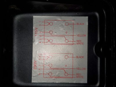
There are two possible 220/240 volt configurations at the motor side:
A) shown in red at the motor cover, but does not mention the little breaker, and the black wire is not used. To use the little breaker here you would need to connect it between either 1 and yellow or 4 and red.
B) shown in the black and white drawing. This one shows the breaker and frankly makes more sense. In this case the red wire is not used and the position of the posts is different from the picture in the motor cover box. The post positions make no difference, you can arrange them however you like.
-M
-Mark
There are two possible 220/240 volt configurations at the motor side:
A) shown in red at the motor cover, but does not mention the little breaker, and the black wire is not used. To use the little breaker here you would need to connect it between either 1 and yellow or 4 and red.
B) shown in the black and white drawing. This one shows the breaker and frankly makes more sense. In this case the red wire is not used and the position of the posts is different from the picture in the motor cover box. The post positions make no difference, you can arrange them however you like.
-M
Last edited:
Nothings changed since post #20. At 1st I just left the the overload protection switch in the same spot it was in and everything ran fine. I read your post and you said the protection switch/little breaker was wrong so I disconnected it. i would like to use it but I am unsure where it goes. I know you said between black and 4 if it was wired useing the black and white it diagram I previously posted in post #20. However I wired it useing the diagram glued to the back of the electrical cover that came with the mill the red wiring diagram from post #25. I'm just wondering where the little breaker should be installed?Where do we stand now? As of post #20 you said you had it working (even though I pointed out the breaker connection was incorrect)
-Mark
- Joined
- Apr 30, 2015
- Messages
- 11,320
If you plan on using the little breaker you should check it for continuity, it may be broken or open circuit since you apparently saw no change when you removed it- in fact you would have seen a problem by now. It is possible that it was tripping immediately and staying open and therefore you would not have seen any issue
(read post #26 for a full review of the wiring options)
(read post #26 for a full review of the wiring options)
Last edited:
I just read post #26 I'm sorry I didn't see all the wiring info the first time I read it. I will post the results after I have rewired with the breaker and checked continuity. I really appreciate your help if you ever have a carpentry question please message me and maybe I can return the favor.If you plan on using the little breaker you should check it for continuity, it may be broken or open circuit since you apparently saw no change when you removed it- in fact you would have seen a problem by now. It is possible that it was tripping immediately and staying open and therefore you would not have seen any issue
(read post #26 for a full review of the wiring options)
- Joined
- Apr 30, 2015
- Messages
- 11,320
Your welcome! I don't do woodworking too often, but thanks