- Joined
- May 4, 2022
- Messages
- 9
Hello everyone,
I took apart my RF-40 milling machine ten years ago and put it in storage until I finished our new house.
Well, the time is good for setting up the machine in my new shop. I've going through all the parts, cleaning, lubing and repainting.
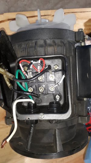
The problem I have is the electrical connection inside the cover on the motor to the terminals there.
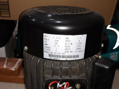
(It came wired for 220/240 and I did draw a map of the wiring when I took it apart, but that map is nowhere to be found)
The manual's wiring diagram is just short of useless for the motor hook-ups. The manual diagram is for the switch, not the motor.
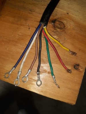
The problem is there are six terminals in the motor electrical box that are labeled 1-6, the wires from/to the switch are color coded.
See attached photos.
The red, yellow and green wire are easy, two hots and a ground. The brown wire is apparently used for 120v, so that leaves me with the
black, white and blue wires to hook up to the terminals in the motor.
Does anyone have one of these machines and can snap a photo inside the cover on the motor to steer me in the right direction?
Any help would be appreciated.
Jack
I took apart my RF-40 milling machine ten years ago and put it in storage until I finished our new house.
Well, the time is good for setting up the machine in my new shop. I've going through all the parts, cleaning, lubing and repainting.
The problem I have is the electrical connection inside the cover on the motor to the terminals there.
(It came wired for 220/240 and I did draw a map of the wiring when I took it apart, but that map is nowhere to be found)
The manual's wiring diagram is just short of useless for the motor hook-ups. The manual diagram is for the switch, not the motor.
The problem is there are six terminals in the motor electrical box that are labeled 1-6, the wires from/to the switch are color coded.
See attached photos.
The red, yellow and green wire are easy, two hots and a ground. The brown wire is apparently used for 120v, so that leaves me with the
black, white and blue wires to hook up to the terminals in the motor.
Does anyone have one of these machines and can snap a photo inside the cover on the motor to steer me in the right direction?
Any help would be appreciated.
Jack