-
Welcome back Guest! Did you know you can mentor other members here at H-M? If not, please check out our Relaunch of Hobby Machinist Mentoring Program!
You are using an out of date browser. It may not display this or other websites correctly.
You should upgrade or use an alternative browser.
You should upgrade or use an alternative browser.
Rotary Phase Converter
- Thread starter matthewsx
- Start date
- Joined
- Jan 2, 2019
- Messages
- 6,545
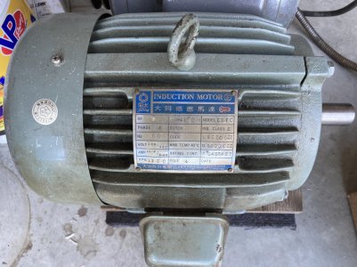
So I bought this 5hp motor a while back and decided it was too big for my lathe. Now I want to DIY a rotary converter. Is it better to buy a static converter or just get a couple of caps and wire them up?
Anybody point me in the right direction for this project? I’ve got a new machine coming and I think I just want to feed it three phase.
John
Anybody point me in the right direction for this project? I’ve got a new machine coming and I think I just want to feed it three phase.
John
- Joined
- Jan 4, 2021
- Messages
- 912
I've never built an RPC, so I can't speak to that. But I have done enough research, and talked to enough people, to know that what I want for MY shop is an RPC. I have no desire for a VFD or a static converter. Both options aren't even 3 phase. They "fake" the third leg, but only to get the motor started, then it cuts out, and is only sending 2 of the 3 legs to the motor. So your motor is only giving you 2/3 (at best) of it's HP rating. Plus, they have to be sized for the motor and are not "portable". And the VFD requires some configuration to not smoke your motor. Static ones are a little more portable, but you can only start one motor at a time (not typically an issue for the one man shop).
The RPC, on the other hand, is true 3 phase, and can be used on any size motor it is rated for (generally, you need an RPC that is double the rated HP of your motors (total). i.e. A 2HP Bridgeport would want a 5HP RPC.
The RPC, on the other hand, is true 3 phase, and can be used on any size motor it is rated for (generally, you need an RPC that is double the rated HP of your motors (total). i.e. A 2HP Bridgeport would want a 5HP RPC.
- Joined
- Jan 2, 2019
- Messages
- 6,545
I’ve used a static converter on my last lathe, and VFD’s on the two lathes I currently own. They’re an excellent upgrade to a manual lathe, I have nothing bad to say about them but I purchased new motors to do it and did the control wiring as it should be.
The new machine I really don’t want to re-wire so I’m ready to do the RPC for this one. The motor only cost me $50 so even if I buy a static converter to do the deed I’m less than $200 into it.
cheers,
john
The new machine I really don’t want to re-wire so I’m ready to do the RPC for this one. The motor only cost me $50 so even if I buy a static converter to do the deed I’m less than $200 into it.
cheers,
john
Nothing "fake" about the third leg generated by a VFD( or the first and second leg for that matter). That's just plain wrong. No more fake than that of a RPC third leg. Nothing is going to be a 100% direct replacement of utility provided 3P service. As for the motor, even an old motor will run just fine off a VFD if all you're doing is providing 60hz 3P AC. Now, if you intend to vary the motor speed via the VFD then yes, you may need an inverter rated motor. My circa 1978 Lagun motor runs like a top off a VFD. I use the variable speed head as intended, and just supply it with basic 60 hz 3P 240VAC. No problem( as did the Rockwell 21-100 before it ). And no idler motor noise/energy consumption. YMMV
Last edited:
- Joined
- Jan 1, 2018
- Messages
- 1,163
I built this phase converter with a 10hp idler about 25 years ago to power my 7.5hp Redstar radial arm saw.
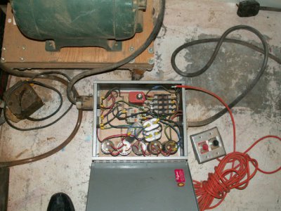
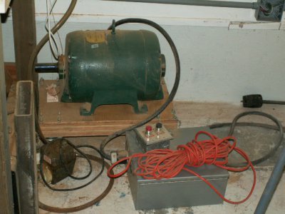
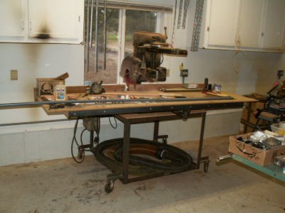
It has powered every one of the 8 or so 3ph machines that I have purchased since. Most of the other 3ph machines have eventually been converted to VFD's but it is really nice to bring a new machine home and be able to power it up imediately.
I initially used some 240v rated capacitors for the starting capacitors and had a few burn out. After I replaced them with 440v rated capacitors I haven't had an issue since. The orange timing relay sets how long the starting capacitors are energized for before they cut out.
Last edited:
- Joined
- Jan 1, 2018
- Messages
- 1,163
Well, in the good old days there used to be a thousand wiring diagrams online. A quick search comes up with a whole bunch of garbage!
The concept is VERY simple, to start the idler engage a large capacitor from one leg of the supply 240v to the generated 3rd leg to get the idler up to speed. Once the idler is up to speed disengage the starting capacitors and the idler will continue to spin on its own generating the 3rd leg for the machine you are powering. The larger this starting cap the faster the idler will come up to speed but the higher the current it will draw in the process. I used the timing relay for this but many others use a potential relay for this. This is all you need.
You can achieve better balance of the voltages across the 3 legs by adding balancing caps from L1 of 240v to the 3rd (generated) leg. And a separate capacitor at about half the size of the first from L2 of the 240v to the 3rd (generated) leg. The balancing capacitors are always hard wired between the 2 legs and the generated 3rd leg, they are never disengaged even when the idler is coming up to speed and the starting capacitors are engaged.
I am using capacitor and capacitors interchangeable in describing the capacitor between the different legs and the starting capacitor since multiple capacitors are usually wired in parallel to create a capacitance of the required value.
I hope my description isn't too confusing? If you can't find anything online I will draw one up on a piece of paper from memory for you and post it.
- Joined
- Jan 31, 2016
- Messages
- 11,474
I do not , but I'm needing one also . I'm following along .Anyone have a wiring diagram?
- Joined
- Jan 1, 2018
- Messages
- 1,163
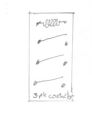
Start with a 3 phase contactor:
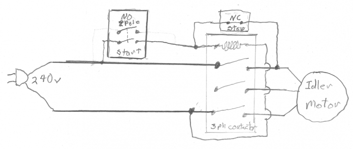
Wire it to be a standard motor starter with separate start and stop buttons. BUT use a 2 pole NO button for the start button:
Wire in the Starting capacitor (bank?):
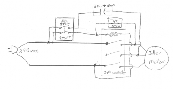
Press and hold the start button. The contactor will close. The starting capacitor will be energized and spin the idler motor up to speed. Once the idler motor is up to speed release the start button. The Idler motor will remain running until the stop button is pressed. Wire the 3 legs of the machine (with its own motor starter) to the 3 legs of the idler motor. Make sure the coil on the motor starter (contactor) of the machine being run is powered by one of the two 240vac legs and NOT the generated 3rd phase leg.
Not shown: Connect common grounds between the 240vac source, Idler motor, and machine being powered.
It is really very easy! From here you can use a timing relay or potential relay to eliminate the 2nd pole of the start button and energize the start capacitor for a set amount of time (adjusting the time for how ever long it takes the idler motor to come up to speed) instead of having to hold the start button closed until the idler is up to speed. I used the timing relay so I could make the start and stop buttons remote from the rest of the wiring.
You can also add "run" capacitors between the 1st leg of 240vac to the idler leg... AND a 2nd capacitor of about half the size of the 1st capacitor between the 2nd leg of the 240vac to the generated leg. Adjust the values (add/remove capacitors wired in parallel) of these balancing capacitors to get roughly equivalent voltages from each of the 3 legs to ground.
SO!... what size capacitors for the starting capacitors and run capacitors? It has been 25+ years so this will have to wait until tomorrow after I get some sleep for me to go out and check the values I used for my 10hp motor.
P.S. OK, a 2 pole contactor could be used. 3 pole contactors are so cheap on ebay I just always use 3 pole contactors even for my single phase machines.

Wire it to be a standard motor starter with separate start and stop buttons. BUT use a 2 pole NO button for the start button:

Wire in the Starting capacitor (bank?):

Press and hold the start button. The contactor will close. The starting capacitor will be energized and spin the idler motor up to speed. Once the idler motor is up to speed release the start button. The Idler motor will remain running until the stop button is pressed. Wire the 3 legs of the machine (with its own motor starter) to the 3 legs of the idler motor. Make sure the coil on the motor starter (contactor) of the machine being run is powered by one of the two 240vac legs and NOT the generated 3rd phase leg.
Not shown: Connect common grounds between the 240vac source, Idler motor, and machine being powered.
It is really very easy! From here you can use a timing relay or potential relay to eliminate the 2nd pole of the start button and energize the start capacitor for a set amount of time (adjusting the time for how ever long it takes the idler motor to come up to speed) instead of having to hold the start button closed until the idler is up to speed. I used the timing relay so I could make the start and stop buttons remote from the rest of the wiring.
You can also add "run" capacitors between the 1st leg of 240vac to the idler leg... AND a 2nd capacitor of about half the size of the 1st capacitor between the 2nd leg of the 240vac to the generated leg. Adjust the values (add/remove capacitors wired in parallel) of these balancing capacitors to get roughly equivalent voltages from each of the 3 legs to ground.
SO!... what size capacitors for the starting capacitors and run capacitors? It has been 25+ years so this will have to wait until tomorrow after I get some sleep for me to go out and check the values I used for my 10hp motor.
P.S. OK, a 2 pole contactor could be used. 3 pole contactors are so cheap on ebay I just always use 3 pole contactors even for my single phase machines.
Last edited:


