
Never bothered to try that. Saw Jo Pi do this and when I tried it I saw a difference. I try things that the You Tubers show and if it works better then I just do it. I have adapted a lot of Jo Pi stuff and it has made my life easier and the results better.

-
Welcome back Guest! Did you know you can mentor other members here at H-M? If not, please check out our Relaunch of Hobby Machinist Mentoring Program!
You are using an out of date browser. It may not display this or other websites correctly.
You should upgrade or use an alternative browser.
You should upgrade or use an alternative browser.
Rotary table securement
- Thread starter finsruskw
- Start date
- Joined
- Feb 21, 2022
- Messages
- 771
If there difference, it is usually due to the head tram or play in the gibs if the knee or spindle are moved.
I would expect that if your table has excess play it would even itself throughout one revolution and still remain true to the centre hole.
If I had a difference between clocking the spindle from the table and clocking the table from the spindle, I would not know which one is correct.
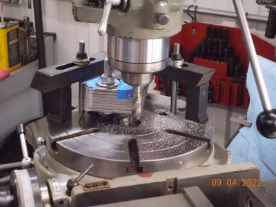
Here is a simple modification I made for quickly and accurately setting up my rotary table.
I would expect that if your table has excess play it would even itself throughout one revolution and still remain true to the centre hole.
If I had a difference between clocking the spindle from the table and clocking the table from the spindle, I would not know which one is correct.
Here is a simple modification I made for quickly and accurately setting up my rotary table.
- Joined
- Sep 22, 2019
- Messages
- 942
- Joined
- Feb 1, 2015
- Messages
- 9,623
I align my mill spindle with the RT axis by mounting a piece of round stock at the center of the table and using an end mill to skim cut a cylinder by rotating the table. By definition, that surface will be concentric with the RT axis. Then I use my edge finder to find the edges in both x and y directions and zero my DRO accordingly. This will position my mill spindle to within a few tenths.
- Joined
- Feb 21, 2022
- Messages
- 771
What type of edgefinder do you use that can find the centre of a disk within tenths?I align my mill spindle with the RT axis by mounting a piece of round stock at the center of the table and using an end mill to skim cut a cylinder by rotating the table. By definition, that surface will be concentric with the RT axis. Then I use my edge finder to find the edges in both x and y directions and zero my DRO accordingly. This will position my mill spindle to within a few tenths.
Why not use an indicator?
Are you using a jig borer with a tenth DRO?
Have you ever checked the hole in the RT after performing the milling of the disc? Perhaps that may show the same position, then you won't need to mill a piece every time.
A check to see if the hole is not concentric with the RT axis is to first find the centre with a DRO. Then index 90 degrees and check again repeat for 180 and 270 degrees. If the reading is the same at all positions then the hole is concentric with the RT axis and can then be accurately used as the reference for the centre of rotation.
RJ, I can see how you would get centered that way. That is the circular version of skimming a piece of metal with an end-mill and setting zero. It looks to me that it would be more steps then I do to get the same results. I did something similar in the beginning bu dropping an MT2 shaft in the RT and dialing it in.
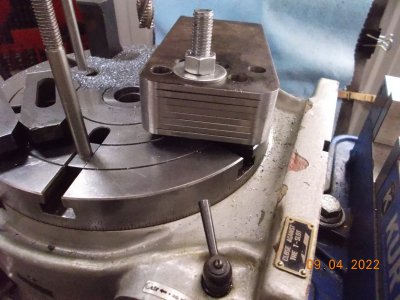
Parlo, my mill is not big enough to put two vises on it and clamp the RT on top. It is a PM 30 with a 6" Grizzly RT. My RT clamps directly to the table with keys. The keys are hand filed to obtain .0002 over 6" in the Y axis when you sweep the base. You push on the right hand side and it has stayed in this tolerance for the last 3 years. I installed a sliding plate on the base to use as a set up referance. I set eveything up with the RT at 0-0 degress and the table locks snubbing it.
I mount the RT to the table. I use an straight shank to MT2 adapter. Using an R8 collet or end-mill holder, I move it around until the adapter slides up and down without rubbing. For the purpose of rounding off the corners on the blocks in the picture above, I wouldn't go any further. If I want to go further, I set the DTI on the table and spin it around and adjust it until it read .0001" out of round.
You state you wouldn't know which way was right. In my case I measured the hole diameter. You dial in the center hole in and lock it down. With a new end-mill and perfect DRO settings you do a 1" diameter hole. If it comes out say 1.0015 you wouldn't think anything of it. You redial it by spinning the table. Now it reads 1.0005. The first reading is because the RT is ever so slightly out of alignment with the spindle. For most applications it will be fine, but for the same amount of effort, I can get a more accurate result.
There are lots of different ways of mounting a vise or RT and dialing it in. I dialed in the hole until I saw the table spinning method a couple of years ago and I got better results. I get good tangent lines and blends and better placed and sized holes for no extra work. If I pushed on the RT and saw slop in it, I would get rid of it. If there is a simple way to get a 300 lb hobby table mill more accurate , I'm all for it.
- Joined
- Feb 1, 2015
- Messages
- 9,623
I use one of these types for locating work edges: https://www.amazon.com/edge-finder/s?k=edge+finder I have demonstrated to my self that I can repeatedly locate an edge to to .0001". To center the RT, I use the same procedure that I use to locate the center of a cylindrical boss on the mill, namely, find left side of the boss, zero x axis, find the right side of the boss and hit 1/2 function key to set x axis zero at center of cylinder. Then I repeat for y axis. This procedure totally eliminates any runout and backlash issues.What type of edgefinder do you use that can find the centre of a disk within tenths?
Why not use an indicator?
Are you using a jig borer with a tenth DRO?
Have you ever checked the hole in the RT after performing the milling of the disc? Perhaps that may show the same position, then you won't need to mill a piece every time.
A check to see if the hole is not concentric with the RT axis is to first find the centre with a DRO. Then index 90 degrees and check again repeat for 180 and 270 degrees. If the reading is the same at all positions then the hole is concentric with the RT axis and can then be accurately used as the reference for the centre of rotation.
My 12" RT is semi-permanently located on my RF 30 clone. Rather than an MT taper , it has a 1" cylinder and my most used mounting fixture is a 4" 3 jaw chuck, making the center hole inaccessible. Much of the work that I did involved machining a cylindrical feature anyway. If I were inclined, I could set up a reference tooling ball on the frame of the RT and set my DRO absolute coordinates to that ball and apply an offset for the RT axis which would save me machining the cylinder. So far, I haven't been bothered.
When I use the RT in the vertical position, I can use a modified procedure to locate the the RT axis. I cut a cylinder from above, using the end of the end mill, then find the center of the y axis as above. I use a digital dial indicator to locate the top of the cylinder. Measuring the diameter with a micrometer, I can determine the vertical offset to the RT axis. I use the TTS tool holding system on the RF 30 clone and can determine my tooling offset from the dial indicator for each tool used. The dial indicator reads in tenths so my positioning is good to a couple of tenths.
My 6" RT, set up as a 4th axis on the Tormach CNC, is used as a vertical RT as it would serve as no useful function mounted horizontally. It has a 5" 3 jaw chuck for a work mounting fixture. Given that 3 jaw chucks are notorious for having runout, the above procedure is most expedient for alignment. Because it takes up too much table real estate , it is mounted only when needed and I have to go through an alignment procedure each time. There are machining work arounds on a CNC mill negating the need for an RT so I seldom have need of it.
- Joined
- Jan 4, 2021
- Messages
- 1,822
Here is Joe Pie's general discussion on rotary tables, including centering them on the mill spindle:Well, I guess I'll either have to remove the vise or move it over as I do not have enough travel on the X axis to center the quill over the hole.
I could squeeze by if I used one of the vise hold down holes for the base end of the RT.
It would be close 1/4's though.
Always something
Can you expound on this?
I must be dense or something this AM!!
I use a Sherline 4" RT on my mini mill since it is the perfect size; it has a 7/16" hole and 3/8-16 tapped center hole which aids alignment of chucks and other accessories. To center it I place a 7/16" Ø drill blank in an R8 collet and move the mill table in X- & Y- until the drill blank enters the hole in the RT smoothly. If I need more precision, I use a DTI as Joe shows in the video.

I have my 3" vise located so the centerline of the spindle can be 1" left of the edge of the jaws (can mill a part extending 3/4" outside of the jaws with a 1/2" end mill), which leaves space for the RT (and other fixtures) on the right side of the table, allowing me to "reach" the circumference of a 4" circle.
- Joined
- Jan 4, 2021
- Messages
- 1,822
Clever deconstruction of a Blake Coaxial Centering Indicator:I saw this hand made tool on Youtube for finding the centre of a hole.
