- Joined
- Apr 21, 2015
- Messages
- 612
I've been working on my lathe off and on over the past several weeks or months, but I've been hesitant to start a thread documenting my progress (or lack thereof!) for fear of embarrassing myself.
I'm increasingly confident that I'm going to end up with a very precise lathe rather than a very large pile of cast iron dust and tears, so I'm finally willing to share my progress.
After creating a new cross-slide for my lathe some time ago, I'd already spent a lot of time scraping in the compound and cross slide. But I decided to tackle a far larger project.
I've taken Richard King's class twice now (and I'm about to help out with a third) but I know full well there is no way to really learn something without actually doing it (and even better, trying to explain what you're doing to others). So, despite my old Wards/Logan being in perfectly (well ... "acceptably") useable shape to begin with, I decided to scrape in the bed ways, headstock, saddle, and tailstock. I rationalized that this was "my first lathe" and even if I ended up with an expensive and shameful pile of worthless cast iron, I'd learn something in the process.
As expected, it's been a terrific learning experience.
I decided to attempt the inner ways and tailstock first before tackling the outer ways and carriage. I thought this wise because in case I totally screwed up, the tailstock is less critical than the carriage. It took an embarrassingly long time for me to realize that the headstock also rides on the inner ways, though, so if I screwed them up I was still pretty much SOL.
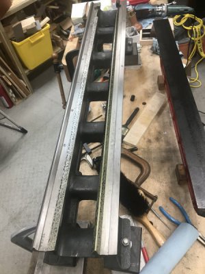
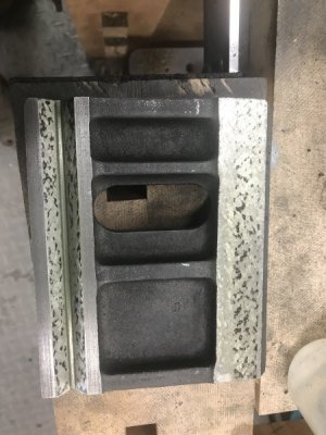
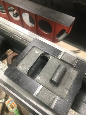
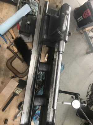
Anyway, I'm happy to report that after a LOT of work, I've got the inner ways and tailstock base scraped in to about 0.0006" with decent bearing over the entire 42" length of the bed:
If I'm reading Connelly correctly, I think the standard for this test is under less than 0.0008". The width of the tailstock base is only about 4" and the level is calibrated to 0.0005"/10" so, if my math is right, each division on my level shows about 0.0002" of deviation. Three divisions max deviation is under the standard. Whoopee.
Actually, I've still got just a bit more fine tuning left. I'd like to get a little bit more bearing points on the far side of the rear fee way, as well as a few more on the bottom of the tailstock base (it's bearing across the entirety of all three surfaces, but I'd like to get a few more PPI). I'm pretty sure I can improve 0.0006" slightly but I'm pretty satisfied already (considering the stack of tolerances).
Interestingly, the far side of the inner inverted-fee way needed the most scraping. Not sure why this would be unless it was out a bit when it left the factory.
I'm leaving out an awful lot of things that I didn't document, but here's the rough outline of getting to this point. I'll try to update this thread with more thorough details as I tackle the outer ways, headstock, tailstock top, and carriage.
Step zero was to scrape in a 36" straightedge. It's slightly shorter than my bed, but there's no way I'd have been able to manhandle a larger straightedge. As it was, I really wish I'd acquired a plain casting without the angled edge for large dovetails. The additional weight of the dovetail feature put it right at the edge of what I can manage by myself (my straightedge weighs about 70 pounds if I recall correctly).
Another (critically important!) preliminary step was to determine what to use as the "datum plane." I'd heard from Scott Logan himself that the flattened tops of the inverted vee ways on Logan lathes were ground at the factory at the same time and with the same setup as the ways themselves. Since the tops of the vees receive no wear, this eliminated a lot of what Richard calls "detective work." After a good stoning to remove the raised burrs from 70+ years of nicks and dings, I had an excellent (and convenient!) reference plane waiting for me.
Connelly calls this a secondary reference/datum. For other manufacturers, you'll have to look for unworn edges on the flat ways, or use the bottom of the rear way to determine the original datum plane. After just one lathe job I'm convinced that if I ever work on a lathe that doesn't have the tops of the vees pre-ground to be coplanar with the real datum (the ways themselves) the very first thing I'd do on a refurbish job would be to make the tops of the vees a secondary datum. It's incredibly convenient to be able to just lay something flat across the ways to indicate from instead of having to balance/clamp 1-2-3 blocks and parallels.
The datum plane is everything when it comes to precise alignment and an accurate lathe. Literally everything on the lathe is adjusted relative to this plane. It's worth spending an awful lot of effort ensuring that all points on this plane are as coplanar as possible. Many years ago, I tried to level my lathe using shims. Trust me, screws/nuts (or paired wedges) are the only way to go for the level of precision required. You'll drive yourself insane trying to get things level (planar) with shims.
While it's only necessary to ensure the datum plane is truly flat, and not to align it with any particular plane, trust me that it's worth the effort of making the datum plane truly level. It's awfully convenient to be able to just throw your level onto things to see if they are parallel to the datum plane.
It's also worth calibrating your level instead of always ensuring you have it oriented in the same direction (something I try to do anyway, but am bound to screw up occasionally). The process is easy and satisfying (and likely documented elsewhere on this site).
I carefully re-leveled the bed at the start of each day's work (and often once or twice during a session, especially after jostling the bed or causing heavy vibration from rough scraping things nearby. Just the tiniest movement of the nuts on the leveling feet is enough to move things out of level by a couple tenths. I have the whole thing supported by a massive maple workbench, but temperature and humidity variations are definitely enough to move the bed out of alignment slightly from day to day.
Here's what level looks like:
I started by scraping the inner flat way. The first blue ups showed more wear in the middle than on the ends, unsurprisingly. Because the area under the headstock is fixed and has no wear, I first tried to leave that area alone as much as possible. I thought I was being smart by "tipping in" the scraping and doing most of the scraping at the tailstock end. Naturally, this ended up with the way angled downward toward the tailstock relative to the datum plane. No bueno. So I ended up needing to remove a bit of metal at the headstock end anyway.
Note that the flat way needs to be coplanar with the datum plane in both dimensions (left to right, as well as fore and aft). It's very easy to confuse yourself when indicating in one direction if you're also out in the other.
In case it isn't obvious, here's how I indicated to ensure things are parallel to the datum plane:
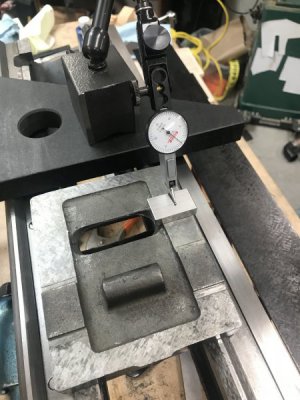
In this image, I've got a piece of precision granite across my datum plane. Just rest the the base of your surface gauge or indicator stand on this, and use a small parallel or side of a gage block to average out the points on a scraped surface.
I discovered a pretty significant nick in one corner of my mag base, by the way, that was causing me no end of grief trying to get repeatable results. A quick stoning fixed the problem, but for a while I thought I was losing my mind.
As I mentioned it's important to realize you may have tipped the flat way in one of two dimensions. At one point I was trying to determine how far the flat way was tilted toward the tailstock after my initial scrape, but I just couldn't seem to get repeatable results. After several attempts, lots of head scratching, walks, and countless cups of coffee, I finally realized the way was also tipped over a thou toward the back of the lathe as well as left to right. Because I wasn't always measuring in the precise middle of the way, my results would vary.
So I rigged up this ghetto King-Way to at least perform this one measurement reliably:
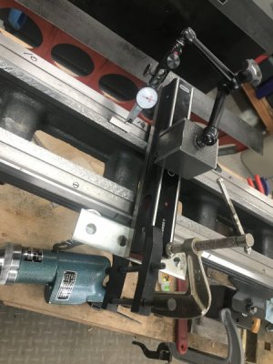
I just super glued a couple washers on a flat bar to create a two point reference, and clamped it to the granite square or level I placed across the vees. This photo is a bit of a lie. I only used this setup to measure the flat way (and ensure I was indicating at the same offset from the edge of the way). I didn't actually use it for the vee ways. The front edge of my lathe is not precision ground (you can still see the rough abrasive grinder/saw marks). It's not flat enough for anything super critical, but it was enough for me to figure out how much I needed to correct left to right.
Hope this all makes sense. I've learned quite a bit in the process, and doubt I've covered half of it, but I hope this is at least somewhat interesting and useful.
Doubtless I'm still making other boneheaded mistakes, but I'll continue to share. Please don't hesitate to correct me if I'm doing something wrong or if there's some easier way.
I'm increasingly confident that I'm going to end up with a very precise lathe rather than a very large pile of cast iron dust and tears, so I'm finally willing to share my progress.
After creating a new cross-slide for my lathe some time ago, I'd already spent a lot of time scraping in the compound and cross slide. But I decided to tackle a far larger project.
I've taken Richard King's class twice now (and I'm about to help out with a third) but I know full well there is no way to really learn something without actually doing it (and even better, trying to explain what you're doing to others). So, despite my old Wards/Logan being in perfectly (well ... "acceptably") useable shape to begin with, I decided to scrape in the bed ways, headstock, saddle, and tailstock. I rationalized that this was "my first lathe" and even if I ended up with an expensive and shameful pile of worthless cast iron, I'd learn something in the process.
As expected, it's been a terrific learning experience.
I decided to attempt the inner ways and tailstock first before tackling the outer ways and carriage. I thought this wise because in case I totally screwed up, the tailstock is less critical than the carriage. It took an embarrassingly long time for me to realize that the headstock also rides on the inner ways, though, so if I screwed them up I was still pretty much SOL.
Anyway, I'm happy to report that after a LOT of work, I've got the inner ways and tailstock base scraped in to about 0.0006" with decent bearing over the entire 42" length of the bed:
If I'm reading Connelly correctly, I think the standard for this test is under less than 0.0008". The width of the tailstock base is only about 4" and the level is calibrated to 0.0005"/10" so, if my math is right, each division on my level shows about 0.0002" of deviation. Three divisions max deviation is under the standard. Whoopee.
Actually, I've still got just a bit more fine tuning left. I'd like to get a little bit more bearing points on the far side of the rear fee way, as well as a few more on the bottom of the tailstock base (it's bearing across the entirety of all three surfaces, but I'd like to get a few more PPI). I'm pretty sure I can improve 0.0006" slightly but I'm pretty satisfied already (considering the stack of tolerances).
Interestingly, the far side of the inner inverted-fee way needed the most scraping. Not sure why this would be unless it was out a bit when it left the factory.
I'm leaving out an awful lot of things that I didn't document, but here's the rough outline of getting to this point. I'll try to update this thread with more thorough details as I tackle the outer ways, headstock, tailstock top, and carriage.
Step zero was to scrape in a 36" straightedge. It's slightly shorter than my bed, but there's no way I'd have been able to manhandle a larger straightedge. As it was, I really wish I'd acquired a plain casting without the angled edge for large dovetails. The additional weight of the dovetail feature put it right at the edge of what I can manage by myself (my straightedge weighs about 70 pounds if I recall correctly).
Another (critically important!) preliminary step was to determine what to use as the "datum plane." I'd heard from Scott Logan himself that the flattened tops of the inverted vee ways on Logan lathes were ground at the factory at the same time and with the same setup as the ways themselves. Since the tops of the vees receive no wear, this eliminated a lot of what Richard calls "detective work." After a good stoning to remove the raised burrs from 70+ years of nicks and dings, I had an excellent (and convenient!) reference plane waiting for me.
Connelly calls this a secondary reference/datum. For other manufacturers, you'll have to look for unworn edges on the flat ways, or use the bottom of the rear way to determine the original datum plane. After just one lathe job I'm convinced that if I ever work on a lathe that doesn't have the tops of the vees pre-ground to be coplanar with the real datum (the ways themselves) the very first thing I'd do on a refurbish job would be to make the tops of the vees a secondary datum. It's incredibly convenient to be able to just lay something flat across the ways to indicate from instead of having to balance/clamp 1-2-3 blocks and parallels.
The datum plane is everything when it comes to precise alignment and an accurate lathe. Literally everything on the lathe is adjusted relative to this plane. It's worth spending an awful lot of effort ensuring that all points on this plane are as coplanar as possible. Many years ago, I tried to level my lathe using shims. Trust me, screws/nuts (or paired wedges) are the only way to go for the level of precision required. You'll drive yourself insane trying to get things level (planar) with shims.
While it's only necessary to ensure the datum plane is truly flat, and not to align it with any particular plane, trust me that it's worth the effort of making the datum plane truly level. It's awfully convenient to be able to just throw your level onto things to see if they are parallel to the datum plane.
It's also worth calibrating your level instead of always ensuring you have it oriented in the same direction (something I try to do anyway, but am bound to screw up occasionally). The process is easy and satisfying (and likely documented elsewhere on this site).
I carefully re-leveled the bed at the start of each day's work (and often once or twice during a session, especially after jostling the bed or causing heavy vibration from rough scraping things nearby. Just the tiniest movement of the nuts on the leveling feet is enough to move things out of level by a couple tenths. I have the whole thing supported by a massive maple workbench, but temperature and humidity variations are definitely enough to move the bed out of alignment slightly from day to day.
Here's what level looks like:
I started by scraping the inner flat way. The first blue ups showed more wear in the middle than on the ends, unsurprisingly. Because the area under the headstock is fixed and has no wear, I first tried to leave that area alone as much as possible. I thought I was being smart by "tipping in" the scraping and doing most of the scraping at the tailstock end. Naturally, this ended up with the way angled downward toward the tailstock relative to the datum plane. No bueno. So I ended up needing to remove a bit of metal at the headstock end anyway.
Note that the flat way needs to be coplanar with the datum plane in both dimensions (left to right, as well as fore and aft). It's very easy to confuse yourself when indicating in one direction if you're also out in the other.
In case it isn't obvious, here's how I indicated to ensure things are parallel to the datum plane:

In this image, I've got a piece of precision granite across my datum plane. Just rest the the base of your surface gauge or indicator stand on this, and use a small parallel or side of a gage block to average out the points on a scraped surface.
I discovered a pretty significant nick in one corner of my mag base, by the way, that was causing me no end of grief trying to get repeatable results. A quick stoning fixed the problem, but for a while I thought I was losing my mind.
As I mentioned it's important to realize you may have tipped the flat way in one of two dimensions. At one point I was trying to determine how far the flat way was tilted toward the tailstock after my initial scrape, but I just couldn't seem to get repeatable results. After several attempts, lots of head scratching, walks, and countless cups of coffee, I finally realized the way was also tipped over a thou toward the back of the lathe as well as left to right. Because I wasn't always measuring in the precise middle of the way, my results would vary.
So I rigged up this ghetto King-Way to at least perform this one measurement reliably:

I just super glued a couple washers on a flat bar to create a two point reference, and clamped it to the granite square or level I placed across the vees. This photo is a bit of a lie. I only used this setup to measure the flat way (and ensure I was indicating at the same offset from the edge of the way). I didn't actually use it for the vee ways. The front edge of my lathe is not precision ground (you can still see the rough abrasive grinder/saw marks). It's not flat enough for anything super critical, but it was enough for me to figure out how much I needed to correct left to right.
Hope this all makes sense. I've learned quite a bit in the process, and doubt I've covered half of it, but I hope this is at least somewhat interesting and useful.
Doubtless I'm still making other boneheaded mistakes, but I'll continue to share. Please don't hesitate to correct me if I'm doing something wrong or if there's some easier way.

