
As I have read many times here, "we like pictures". Sure, if it is not too much of a bother, I would enjoy seeing the pictures. Hopefully, I will not have to lift anything when moving my lathe. This forum has been a great source of information and will cause me to rethink the layout of my shop. So, moving to improve operation will likely happen. Hopefully, it will be an uncommon activity.@tredding i had a solution for my 12 X37 that you'd might appreciate. I had to fabricate my own stand, and so I made some blocks under the headstock that would take 1" NF bolts, I found some 4.25 inch phenolic wheels with a 1" bore. When I have to move the lathe, all I do is lever up, put the wheels on, and then drive it across the shop like a shopping cart. The tailstock end is easily light enough to lift and push/pull, even for an old guy like me.
-- if you are interested I could take a pic or 2 and post here.

-
Welcome back Guest! Did you know you can mentor other members here at H-M? If not, please check out our Relaunch of Hobby Machinist Mentoring Program!
You are using an out of date browser. It may not display this or other websites correctly.
You should upgrade or use an alternative browser.
You should upgrade or use an alternative browser.
Setting-up the PM 1236-T Lathe
- Thread starter Titanium Knurler
- Start date

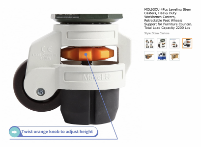
This is a great thread. This is the caster I installed on the PM-728VT stand and plan to install on the PM-1236 when it arrives in November 2022. Four for about $45 at Amazon. Four support 2200 pounds, so six should easily support the PM-1236 and stand. https://www.amazon.com/gp/product/B09V6GCLXN/ref=ppx_yo_dt_b_search_asin_title?ie=UTF8&th=11.) Outriggers with Casters
This is what comes with the lathe: a cast iron puck, a bolt and a nut.
View attachment 285613
Here is a configuration that I considered from a piece of equipment at work
View attachment 285617
That arrangement was appealing because it lowered the CG of the cabinet but I wanted casters that I could adjust the leveling foot with a wrench rather than a plastic wheel that most of the casters have, in addition the bent arrangement of the outrigger would get in the way of the cabinet doors. I went with straight outriggers. I used three 1/2”x 4”x23” pieces of 1018 cold finish steel flat. The cabinet is 15” wide so this gave me a 4” x 4” area extending from the cabinet to attach the casters. All the holes are 3/8” except the larger hole for the M16 leveling foot which is 3/4”. The outriggers were then painted and attached to the base. The holes on the base are a different size and offset a bit so you have to take that into consideration when measuring. I used a spacer to account for the different diameters:
View attachment 285618. View attachment 285619
View attachment 285620. View attachment 285621
I used Carrymaster ALC1000 casters. The outriggers were attached to the cabinet and the casters attached to the outriggers using 3/8” x 1-3/4” bolts.
View attachment 285622. View attachment 285623
View attachment 285624. View attachment 285625
I used 2” fender washer and an M16 coupler nut that had been cut in half to act as a lock nut on the leveling foot.
View attachment 285627. View attachment 285629
I am then able to make fine adjustments of the leveling foot with a small wrench and then secure the position with a larger wrench on the coupling nut.
View attachment 285630. View attachment 285631
I added some equipment pads to help keep the lathe from walking but I think they are overkill. The machine is very solidly in position without them.
View attachment 285632. View attachment 285633
This added about 5” to the cabinet height. The PM puck-and-bolt is about 1-1/2” so there is a net gain of about 3-1/2” over the puck-and-bolt configuration.
View attachment 285634
That’s it for the outriggers. Tomorrow I will try to do the equipment mounts and hopefully the day after the baseplate.
Attachments
Is it leveling or combating twist? Terry - W6LMJMikey, the baseplate is threaded and the jack screw goes into those threads. When the screw is advanced upward it lifts that portion of the tailstock footing. For example, when I was leveling the lathe the side of the tailstock toward the operator was a bit low. I loosened the nut on the anchor bolt, lifted that corner by advancing the jack screw then re-tightend the nut on the anchor bolt. I repeated this is small increments until the lathe was level, then I tightened the lock nut on the jack screw. This took a total of about a quarter turn on the jack screw. The pointed end of the jack screw is not used. I used jack screws because they have a nice fine 1/2-20 thread, they are hardened and I can use the small hardened rod that comes with them to make adjustments by hand. Also, they are only $8 from Starrett. I didn’t know Starrett made anything for $8. I hope this helps.