Sherline tailstock chuck upgrade?

fcs

Registered
Registered
Joined
Jul 4, 2020
Messages
87
I am wondering if there is any affordable chance of upgrading the tailstock drill chuck on my Sherline lathe. My main use of the lathe is making fishing rod ferrules, and a whole lot of drilling and reaming in thin-walled pieces is involved. I have a feeling that the Rohm chuck that came with it is not the most precise. I really don't know how to assess the quality of a replacement other than price. A $100 chuck like this Jacobs 3/8 looks good to me: https://www.mscdirect.com/product/details/08590655 and is in my budget. If a better chuck would cost way more I would pass.

Since someone would ask, the reason I suspect my chuck is this discussion on the Beginners forum:
If I put a dead center in the headstock and a quality drill rod in the tailstock chuck, I can consistently move the drill rod around wrt to the dead center by rotating the MT0 chuck arbor in the tailstock. I hope that makes some sense.
 
Last edited:
I am wondering if there is any affordable chance of upgrading the tailstock drill chuck on my Sherline lathe. My main use of the lathe is making fishing rod ferrules, and a whole lot of drilling and reaming in thin-walled pieces is involved. I have a feeling that the Rohm chuck that came with it is not the most precise. I really don't know how to assess the quality of a replacement other than price. A $100 chuck like this Jacobs 3/8 looks good to me: https://www.mscdirect.com/product/details/08590655 and is in my budget. If a better chuck would cost way more I would pass.

Since someone would ask, the reason I suspect my chuck is this discussion on the Beginners forum:
If I put a dead center in the headstock and a quality drill rod in the tailstock chuck, I can consistently move the drill rod around wrt to the dead center by rotating the MT0 chuck arbor in the tailstock. I hope that makes some sense.
This doesn't necessarily mean that the chuck is bad. It could be the tailstock taper, the drill arbor, or the chuck is dirty, or out of spec. You ought to determine which one it is before throwing money at the problem. Could be swarf in the tailstock taper, or in the arbor to chuck interface. Or the chuck itself. So methodically check them all out. There's probably more things, but I'll let folks with more Sherline experience jump in.
 
Sherline basically acknowledges the variation in their tail stocks by selling adjustable adapters for tail stock tools. The trick to them is your tail stock must be in good condition to start with and to allways insert them in the same position relative to the tail stock ram, so you need some markings on the adapters and the ram.

Eric
 
I intend to replace the spindle in the tailstock of my lathe. I purchased a new, unground spindle from Sherline. I plan to turn it down to a close fit in the tailstock. Additionally, I plan to turn down the spindle with the spindle off center, to counteract the misalignment of the tailstock with the headstock. I plan to drill out, plug, and re-tap the threads in the new spindle -- to compensate for the spindle being turned down off center.
 
I intend to replace the spindle in the tailstock of my lathe. I purchased a new, unground spindle from Sherline. I plan to turn it down to a close fit in the tailstock. Additionally, I plan to turn down the spindle with the spindle off center, to counteract the misalignment of the tailstock with the headstock. I plan to drill out, plug, and re-tap the threads in the new spindle -- to compensate for the spindle being turned down off center.
As another Sherline lathe owner, I'm interested to see how your tailstock spindle alignment works out. I understand what you plan to do and acknowledge the difficulty of getting that precisely correct. Keep us posted!
 
Have you thought about using blank end mill holders and boring them out from the live chuck with them inserted into the tail stock.

You could put witness marks on them so they get inserted the same every time.

Stu
 
As another Sherline lathe owner, I'm interested to see how your tailstock spindle alignment works out. I understand what you plan to do and acknowledge the difficulty of getting that precisely correct. Keep us posted!
Forty Niner,

I originally described my tailstock spindle alignment idea in the thread on this page, in the thread "Sherline Tailstock Misalignment". You pointed out a problem with my set up, and suggested solutions. That was two years ago. Instead of pursuing this idea to completion, I modified a belt sander for grinding my own HSS cutting tools. Next, I designed and made a tangential tool holder that works that mounts both in Sherline's 3/8" Insert Holder Tool Post (7600) and Compound Slide (1270). I've been stuck on designing sharpening fixtures for the tangential tool bit.

With the recent passing of Mikey, I have become motivated to go back to the beginning with my lathe, and use what I have learned to get my lathe into good shape. To me, good shape includes a tailstock spindle that has a tight sliding fit in the tailstock housing, and a tailstock spindle that has minimal misalignment (less than 0.001 inch) to the headstock . In lieu of finishing the tantential tool holder project, I have ordered the A R Warner kit #4, of indexable 1/4-inch turning and 3/8-inch boring tools with HSS inserts.

Karl
 
I received the A R Warner Kit #4, of 1/4-inch turning and 3/8-inch boring tools. I ordered it from Little Machine Shop.

I inspected the inserts in the kit, using a 10x loupe. I was surprised by the variation among the nose radii. A couple points did not have a ground radius.

Wondering whether I experienced a fluke, I ordered more inserts directly from A R Warner: 2 each of CCMW 2.1.5-0.5 and CCMW 2.1.5-1 in T-15 HSS. The nominal nose radii are 1/128 inch and 1/64 inch, respectively, at the 80-degree points.

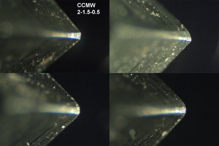
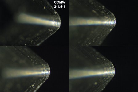
Today, I viewed the 80-degree points of the four inserts (directly from A R Warner) under a light microscope. I took photos. There is less variation among the nose radii of these inserts, compared to the inserts in the kit. The variation is clearly visible, though -- especially with the inserts with 1/128-inch radii. Here are photos, looking from bottom of insert toward the top:

:CCMW 2-1p5-0p5.jpg
CCMW 2-1p5-1.jpg

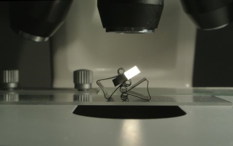
Here is a photo of my set up, with an insert held by a paper clip. A light is shining from the right.
microscope with CMW insert.jpg
Despite the visible variation, I expect that the four inserts will work well. The inserts in the kit seem to be a partial fluke.

Karl
 
Last edited:
I returned the AR Warner kit. After receiving it, I realized that for this tailstock-replacement project, I only need one 1/4-inch shank insert tool holder -- for the Sherline compound slide. I replaced the kit with a Micro 100 90° turning and facing indexable toolholder, model 10-321:
1704745685885.png
I also purchased three Micro 100 carbide CCMT 2-1.5-1 inserts for it.
I like that the toolholder accepts both Micro 100 carbide and the AR Warner T-15 HSS inserts.
For now, I following Leo J. St. Clair's recommendation (on page 259 in the book Design and Use of Cutting Tools (1952)) to use HSS to cut steel, due to the low power and rigidity of the Sherline lathe. Carbide needs to run hot and fast on high-strength materials; otherwise, it can wear faster than HSS.
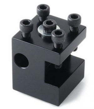
I made a simple bump centering tool, from oversize 3/8-diameter aluminum 6061-T6 stock, to mount in the round port of the Sherline 3/8" Insert Holder model 7600:
1704746231522.png
I cut a piece of 3/8-inch stock 2 inches long. I faced the ends. I used a lathe file on my lathe to reduce the OD of the section that goes in the holder. (OD of stock was 0.377 inch; ID of toolholder is 0.3753 inch). I also filed a flat for the set screws.

I used the bump-centering tool for part the process of aligning the headstock of the lathe with the bed . I used it to reduce the runout of end of a 3-inch long 3/4-inch-diameter aluminum bar sticking out of the Sherline 3.1-inch 3-Jaw Chuck model 1040. I call this bar a "testpiece".

I used the Micro 100 toolholder and a Micro 100 carbide insert to turn down the testpiece, with alternating 0.003-inch and 0.001-inch depths of cut. I measured the OD of the testpiece near the chuck and near the right end, after each 0.001-inch cut, to check the headstock alignment.
I used a dial test indicator mounted in the Sherline 3/8" Insert Holder on the rear of the lathe table as an aid in adjusting the headstock. I took me until 0.62-inch diameter to achieve alignment. Final diameters of the testpiece were 0.6182 inch on the left side, and 06183 on the right side.
Note: At around 0.65 inch diameter, the Micro 100 toolholder and insert started chattering at the beginning of cutting at the right end of the testpiece. Instead of installing a new testpiece, I quickly ground and honed an M-2 HSS turning tool for aluminum. My tool wasn't great, but it let me continue with the existing testpiece.

To turn a replacement tailstock spindle, I need an extra-long and adjustable tailstock center. I need the extended length because my existing spindle has a loose sliding fit in the tailstock; it has horizontal play and I want to minimize that play. I also need the extended length because I am using a quick-change tool post that extends past the left side of the crosslide. To make the center adjustable, I designed it to install in the Sherline Adjustable Tailstock Custom Tool Holder, model 1203:
1704749562001.png

I turned an extended-length center from a 3-inch long piece of oversize 5/8-inch diameter O-1 tool steel. I modeled it after the long interchangeable tip on Mikey's live center. Here is the result:
20240108_extended-length-dead-center.jpg

Karl
 
Last edited:
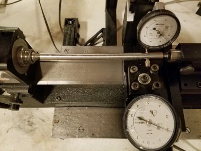
Next: I measured the misalignment of the tailstock, compared to the aligned-to-the-bed headstock. I followed the procedure described by Mikey in posts #19 and #21 in the thread Sherline Tailstock Misaligment. Here is a photo of my setup:
tailstock misalignment measurement 20240111_161923.jpg
In the photo, the dials show the tailstock to be misaligned 0.0020 inch to the rear, and 0.0004 inch above. Due to the loose fit of the spindle in the tailstock case, the readings varied. For example, when I tightened the lockscrew on the tailstock, the horizontal misalignment increased to 0.0027. The vertical misalignment also increased, to 0.00065 inch. I resorted to measuring median values of extremes obtained by pressing the spindle forward, backward, up, and down. The median values were 0.0023 inch to the rear, and 0.00065 inch above.

Regarding the looseness of the spindle: I measured the outer diameter of the spindle to be 0.6179 inch, and the inner diameter of the tailstock case to be 0.6192 inch. That is 0.0013 diametrical clearance. According to a Machinery's Handbook, the clearance range for RC-1 (running and sliding fits) in the nominal size range of 0.40 to 0.71 inch is 0.00025 inch to 0.00075 inch.

My test bar is 5.96 inches long, but the distance of the traverse of the cross slide was only 4.44 inches -- due to interference by the headstock and tailstock. Therefore, I think that actual misalignment of the tailstock is 5.96/4.44 = 1.34 times greater than indicated by the dials. The calculated actual misalignment is 0.0031 inch to the rear, and 0.0009 inch above.

Obtaining these misalignment values took several tries. After the first try, I checked the alignment of the headstock and found that it was no longer aligned with the bed. I realigned it, and locked the headstock into place using blue threadlocking compound as described on page 13 of Sherline's Assembly and Instruction Guide.

My next step will be to make a spindle out of 6061-T6 aluminum, with the Morse taper offset approximately 0.0030 inch from the centerline. The purpose is to develop the procedure. I also want to test the fit of a spindle with 0.0004 inch diametrical clearance in the tailstock case.

Karl
 
Last edited:
Back
Top