Sherline tailstock chuck upgrade?

Karl,

I am following your challenging adventure to improve the tailstock alignment. Thanks for sharing with such detail.
 
I changed my mind. I decided to make a spindle out of 6061-T6 aluminum, without offsetting the Morse-taper socket from the centerline. Making spindle with an offset Morse-taper socket seemed like too big of a leap in developing the procedure. Also, having one without an offset that fits tighter in the tailstock will allow me to measure with less uncertainty the misalignment of the tailstock.

In terms of lathe work, I model the spindle as being 2.375 inches long, with an O-size (0.312-inch diameter) hole drilled 1.875 inches deep down the centerline from one side. A Morse #0 socket begins at 0.350 inch diameter and tapers down to the diameter of the O-size hole. On the centerline of the other side, a 1/4-20 left-hand thread is drilled and tapped to meet the O-size hole.

I started with a piece of 3/4-inch OD 6061-T6 aluminum bar stock, which I cut and faced to 2.375 inches long. This was the workpiece.

I mounted the workpiece in the Sherline 3-jaw self-centering chuck (#1040). I bump-centered the unmounted end. I drilled 1.875 inches deep with an O-size drill. I used a Sherline 3/8"-capacity drill chuck (#1069) and a Sherline Adjustable Trailstock Chuck Holder (#1202). To drill so deep, I drilled in two steps: 1 inch and 0.875 inch. I moved the tailstock to the left by 1 inch after drilling 1 inch. I had set the crosslide as a location reference, for moving the tailstock 1 inch.

After drilling the hole, I removed the chuck from the lathe, with the workpiece still mounted in the chuck. A Morse #0 socket was later bored in the drilled side.

I installed a Sherline four-jaw independent chuck on the lathe. I mounted a Sherline Adjustable Tool Back (#12040) from one of my Sherline adjustable tailstock tools. The Adjustable Tool Back has a Morse #0 shank, which I later used to set the angle of the Sherline Compound Slide (#1270), and which I used to hold the workpiece when I turned down the workpiece OD to fit the tailstock.

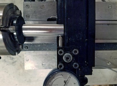
I set the Adjustable Tool Back in the chuck with a 1-inch x 4-inch x 0.010 inch brass shim against the body of the chuck. I pulled the shim out, to create space for movement during tapping in. Here is a photo of the Adjustable Tool Back in the chuck, before pulling out the shim.
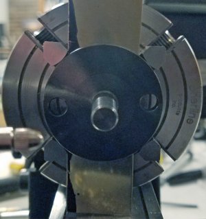
20240120-122957 shim.jpg

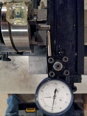
I used a dial-test indicator, mounted on the cross slide to measure the runout of the shank - near the base of the shank and near its end. I adjusted the screws of the chuck to eliminate runout near the base of the shank. I tapped the disk toward the chuck to eliminate runout at the end of the shank. I achieved 0.0001 inch TIR near the base and end of the shank. I then measured the amount of taper of the shank in the x-axis along 0.600 inches of the z-axis at the #1, #2, #3, and #4 chuck screw locations on the circumference. Here are the values, respectively: 0.01541, 0.01542, and 0.01541, and 0.01540 inch. Similar values suggest that the shank is nearly parallel to the z-axis.

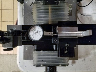
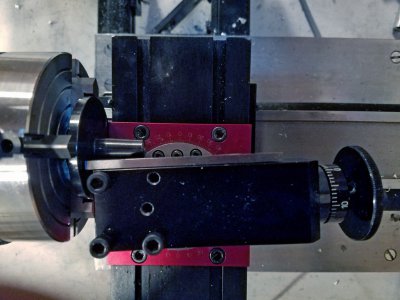
I set the angle of the compound slide against the Morse shank. Here is a photo, taken looking down:
20240120_134345 compound slide.jpg
In the photo, there is a 1-inch wide parallel between the compound slide and the Morse shank. The mounting and adjustment screws of the compound slide were loose. I tightened them while pressing the compound slide, parallel, and shank together.

I removed the 4-jaw chuck and Morse shank from the lathe. I used then again, later.

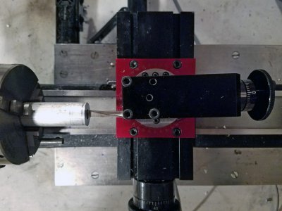
I remounted the 3-jaw chuck and workpiece on the lathe. I used the Sherline High Speed Steel Boring Tool (#11970) to bore the Morse socket. I bored it at 600 rpm with feed rate of 0.5 handwheel rotations per second. I advanced the crosslide to the rear a total of 0.019 inches ((0.350 inch - 0.312 inch)/2 = 0.019 inch). Here is a photo taken looking down:
20240120_140100 boring.jpg
In hindsight, I think it would have been better to have turned the OD of the workpiece smooth at the beginning, and used the Sherline Steady Rest (#1074) to support the workpiece during the boring operation.

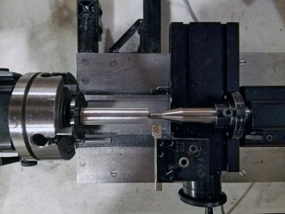
I removed the workpiece from the 3-jaw chuck. I reinstalled the 4-jaw chuck with its Morse shank, and twisted the workpiece onto the Morse shank. I installed my extended-length dead center, and proceeded to turn down the OD of the workpiece to fit the ID (0.6192 inch) of the Tailstock Case. Here is a photo:
20240121_011256 turn down.jpg
The cutting tool is a Micro 100 CCMT 2-1.5-1 carbide insert in a Micro 100 tool holder (#10-3231). Cutting conditions were 600 rpm, one handwheel rotation per second, and depth-of-cuts of 0.005, 0.001, and 00005 inch. Toward the end of turning down, though, I replaced the cutting tool with a brazed carbide Micro 100 AR4 turning tool. The set up was not sufficiently rigid for the carbide insert. The workpiece was tapering 0.0004 inch larger in diameter from left to right, even with 0.0005 inch depth-of-cut and multiple spring passes with the insert. I think that the brazed carbide tool did better because it was sharper. In the end, the diameter was 0.6187 inch left, 0.6187 inch middle. and 0.6188 inch right. My goal was 0.6188 inch. The ID of the tailstock is 0.6192 inch.

Finally, I drilled and cut 1/4-20 left-hand threads in the right end of the workpiece. Toward the end of cutting the threads with a tap, the workpiece slipped on the Morse shank. I removed the workpiece from the Morse shank, wrapped it with paper masking tape for a hand grip, and finished the threads by hand.

I installed the workpiece in the trailstock, as an unfinished spindle. The fit is good. There seems to be room for tighter. Perhaps I will aim for 0.6189 inch diameter next time.

I measured the misalignment of the tailstock as before, with the unfinished spindle at four 90-degree rotations around the z-axis. The horizontal misalignment readings were 0.00238, 0.00252, 0.00247, and 0.00232 inch toward the rear. The vertical misalignment readings were 0.00078, 0.00092, 0.00108, and 0.00090 inch high. The average values are 0.00242 and 0.00092 inches. Those values are with the tailstock screw lose. Tightening the tailstock screw increased the horizontal misalignment by 0.00030 inch; it increased the vertical misalignment by 0.00008 inch.

The traverse along the 5.96-inch long test bar was 4.40 inches. Accounting for the difference increases the misaligment values to 0.00328 inch to the rear and 0.00125 inch high.

I will finish the spindle, by milling a slot in the side.

Karl
 
Last edited:
Since my last post, I machined two tailstock spindles out of 6061-T6 aluminum, with offsetting the Morse-taper socket from the centerline. With both, the offset was insufficient to counteract the misalignment of the tailstock case. With the first spindle, I determined the cause. With the second spindle, the cause is unknown.

I intended to machine the first spindle to have 0.0035 inch offset, but I mistakenly offset the Morse shank of adjustable-tool back by half that amount: 0.00175 inch. I thought that the dial indicator showed 0.0035 inch, but it actually showed +0.00175 inch and -0.00175 inch.

This time, the workpiece did not slip on the Morse shank during thread tapping, because I secured it with blue threadlocking compound. I released the workpiece from the Morse shank by placing the workpiece and the adjustable-tool back in an oven at 400°F. The threadlocking compound smoked at 400°F, and the mostly-completed tailstock spindle fell off the Morse shank.

Using a dial test indicator, I measured the amount of offset of the Morse socket after centering the OD of the spindle in a 4-jaw independent chuck. I measured ±0.00175 inch.

Being that I mistakenly made the spindle with half the required amount of offset, I expected it to counteract half of the misalignment of the tailstock case. It counteracted more than half the misalignment. Therefore, I remeasured the misalignment of the tailstock case, using the aluminum spindle that I previously machined to have no offset (see previous post). While doing so, I discovered that the 1-inch-long machined end of my 6-inch long test bar has a 0.0006 inch taper in its diameter. I compensated for the taper by measuring at the same location on the test bar -- during the zero setting and during the misalignment measurements. I made a few other improvements in my measurement technique. My result this time was that the misalignment of the tailstock is 0.00290 inch to the rear, and 0.0006 inch high. The combined value is 0.00295 inch.

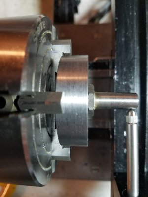
I intended to machine the second spindle-with-offset-socket with 0.0030 inch offset. This time, I set ±0.0030 inch reading with the dial indicator. Another change is that I placed the workpiece on the Morse socket before I performed the offset. I turned the OD of the workpiece concentric with the Morse socket, and then offset the workpiece and socket together. I read the amount of offset on the OD of the workpiece, near the left and right ends. I only needed to turn two screws on chuck, and I did not need to do any more tapping in. The dial indicator read ±0.0030 inch at both ends of the workpiece. Here is a photo:
20240203_161748 shank and workpiece offset together.jpg

I achieved diameters of 0.6188 inch left, 0.6188 inch middle, and 0.6192 inch right, using a Micro 100 brazed carbide tool AR4 -- which I had resharpened by passing the top across Dia-Sharp 325-grit and 1200-grit diamond sharpening cards. I reduced the diameter on the right side to 0.6189 inch using a lathe file. I consider the tailstock case to have 0.6192 inch ID. (Initially, the spindle fit in the tailstock case with significant sliding resistance.)

After drilling and tapping the right end, I removed the second workpiece/spindle from the adjustable-tool back with the oven set at 350°F. This time, the threadlocking compound smoked minimally.

I measured the offset of the Morse socket in the second spindle. To my surprise, the dial-test indicator read only ±0.00235 inch (not the expected ±0.0030 inch). I do not yet know why the offset came out so far from the intended 0.0030 inch.

My machining knowledge, skill, and tools are improving through this challenging adventure.

Karl
 
Last edited:
I’ve enjoyed your project Karl. I am wondering if 6061 alloy was the best choice. I make aluminum fishing rod ferrules and use 7075 which is significantly stronger in terms of tensile strength. It may not make any difference in your application and you may have considered it all ready.

Good choice in breaking the thread locker bond in the oven. The tempering temp for aluminum is only in the 850-900F range and it is easy to exceed that with a torch or even a heat gun.
 
fcs,

I plan to switch to steel after I have successfully made a tailstock spindle with the correct offset in 6061 aluminum, and have milled the slot at the correct location to properly distribute the offset -- to cancel the horizontal and vertical misalignments of the tailstock case. I have a foot-long piece of 11/16-inch diameter 1144 stress-relieved bar stock for it.

On my next aluminum spindle, I plan to NOT use threadlocking compound. Instead, I plan to heat the aluminum workpiece to 165°F and shrink fit it onto the Morse shank. I calculated that later, heating both the aluminum workpiece and steel shank to 350°F will definitely release the workpiece. When I switch to making a steel spindle, I will go back to using threadlocking compound.

Karl
 
Last edited:
With my next (third) aluminum spindle, I achieved the desire 0.0030" offset. This time, I
#1: offset the Morse shank without the workpiece installed on it.
#2: leveled the lathe and placed a camera-hotshoe level on the top of the 4-jaw independent chuck to obtain accurate positions for -0.0030", 0.0000", 0.0000", and +0.0030" runouts at the four jaws. This worked well. I did need to adjust all four jaws, and do some tapping in to obtain the values at both ends of the Morse shank.
#3: installed the workpiece, onto the Morse shank, hot instead of using threadlocker compound. I heat soaked it to 190°F. Unfortunately, the workpiece spun toward the end of cutting the threads. I had not yet scribed the location of the +0.0030 offset, which added work and error later.
#4: measured the runout of the workpiece after installing it on the offset Morse shank. The right end (away from the chuck) had a runout of ±0.0026". That portion of the workpiece had not yet been turned concentric. Being that the workpiece is longer than the Morse shank of the adjustable tool back, setting the offset with a turned, concentric workpiece installed on the shank has potential to achieve an offset that is more consistent along the length of the tailstock spinde.

Here is a photo from #2:
20240209_212700 -0.0030 offset at shank-end.jpg
-
A quick check with the workpiece in the tailstock showed that achieving zero horizontal misalignment was possible.

The next step was to mill a slot in the OD of the workpiece, at the correct location on the circumference, to achieve the required -0.0006" vertical and +0.00029 horizontal offsets to cancel the misalignment of the tailstock case . I decided to do mill the slot with my Sherline 5400 mill and Sherline mill vise, with a V milled into custom soft jaw. I made the soft jaw out of 6061-T6 aluminum. I added a stop to prevent the workpiece from moving in the axial direction as it was turned to find the location of the +0.0030 offset. I also made an angle arm, for setting the posiition of the workpiece for milling. Here is a photo.
20240219_131243 workpiece on mill.jpg
The photo includes a dial-test indicator, which I used to find the location of the +0.0030" offset in the workpiece. I was not able to find the point precisely, being that the needle moves very little in the area of maximum offset. It would have been better to have scribed the workpiece before it slipped on the Morse shank (during threading).

I set the angle arm to inverseSine (0.0006"/0.0030") = 12° from vertical. I milled a 0.050" deep by 0.130" wide slot in the top of the workpiece, between 0.50" and 1.875" from the left side. Doing so completed the aluminum tailstock spindle.

I measured the misalignment of the aluminum spindle in the tailstock case. As before, I used a test bar, centers, and dial indicator. I took four readings each of horizontal and vertical misalignment, measuring with the dead center in the tailstock spindle at 0°, 90°, 180°, and 270° to account for nonconcentricity of the dead center. Averaging the readings and extrapolating to the full length of the test bar, I obtained:
- horizontal misalignment: 0.0001" to 0.0002" towards the front
- vertical misalignment: 0.0002" to 0.0003" high.
This result is gratifying. It shows that that the misalignment of the tailstock can be significantly reduced by this approach.

Karl
 
Last edited:
Congratulations on your perseverance Karl! I wish their were an easier way to accomplish precision tailstock alignment.
 
Congratulations on your perseverance Karl! I wish their were an easier way to accomplish precision tailstock alignment.
Thank you.

I am thinking about machining a tailstock spindle out of 1144 stress-relieved steel.

I am thinking about including a feature in a 1144 spindle: the 1/4"-20 reverse female thread being interference fit in the spindle. Including this feature would allow the Morse #0 socket in the spindle to be reamed during manufacture, to correct any minor error in boring and to smooth the surface. In the future, the feature would allow the threads to be pressed out and the Morse socket to be reamed to renew it. Alternatively, I can skip this feature and shorten a Morse #0 taper reamer to fit in the spindle. Currently, a Morse #0 taper reamer costs $51.57 at McMaster-Carr.

I am thinking about finishing the unfinished tailstock spindle that I purchased from Sherline. Its OD is 0.6250", and it lacks a slot. Is it possible/practical to turn it down to 0.6188" OD with the Morse socket offset by 0.0030"? Completing it would require drilling out the existing threads, replacing them with an interference-fit part that includes new threads.
 
The Morse #0 shank on the Sherline adjustable tool back, p/n 12040, is quite rough. The roughness interferes with adjusting the shank to zero runout in a four-jaw independent chuck.

The Morse shanks are much smoother on the #0M and #1M threaded arbors (p/n 11890 and 11880) for the 1/4-inch and 3/8-inch drill chucks.

I cut a 0.5-inch length of a 1-3/4-inch diameter steel bar of 12L14 that I have. I turned it into a centering fixture for the drill-chuck arbors.

Here is a photo of the #0M arbor on the centering fixture, in a four-jaw independent chuck.
20240224_213436.jpg
An advantage of the centering fixture is that it can also be used with the #1M arbor to provide a centered Morse #1 shank. The threads of the two arbors are the same: 3/8-24.
 
Last edited:
Two caveats:

First Caveat: I have measured significantly different amounts of taper between the Morse #0 arbor, and the adjustable tool back that I used to make the aluminum tailstock spindles: 0.638 inch per foot on the arbor, and 0.629 inch per foot on the adjustable tool back. Engineersedge.com gives 0.624,0 inch + 0.002 inch -0.000 inch as the correct range for a shank. The differences don't inspire confidence.

I am using the leadscrew of my lathe in the measurement, but I don't know its accuracy. I think, though, that the measured amounts between the arbor and adjustable tool back ought to be closer to each other

My initial measurement of taper amount of the arbor gave 0.688 inch per foot. I reported this value in the first version of this post. I think that I misread the dial indicator by one digit (0.001 inch).

Second Caveat: I measured the vertical misalignment of the headstock spindle to the bed. I got 0.002,27 inch rise from left to right, along 2.75 inches of the z-axis. This amount of misalignment renders futile my attempt to measure and cancel the vertical misalignment of the tailstock. For comparison, I measured 0.000,09 inch horizontal misalignment (toward the front from left to right) along the same 2.75 inches.
 
Last edited:
Back
Top