Sherline tailstock chuck upgrade?

Two caveats:

Second Caveat: I measured the vertical misalignment of the headstock spindle to the bed. I got 0.002,27 inch rise from left to right, along 2.75 inches of the z-axis. This amount of misalignment renders futile my attempt to measure and cancel the vertical misalignment of the tailstock. For comparison, I measured 0.000,09 inch horizontal misalignment (toward the front from left to right) along the same 2.75 inches.
Karl,
This is a shortcomming of the Sherline lathe design. 1) The bed is attached to the base by one cap screw at the extreme left end. 2) The bed is painted with a wrinkle finish paint that will compress over time. 3) When you tighten the screw the paint will compress at the screw end but not under the entire headstock, and the bed will flex relative to the base.
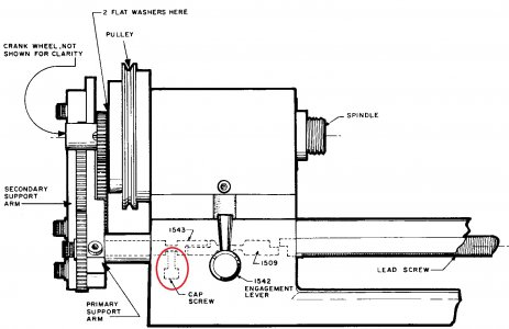
cap screw.jpg

To see the problem remove the screw under the handwheel end of the lathe bed. The bed will straighten out float above the base at the handwheel end.

I solved mine by removing the paint.
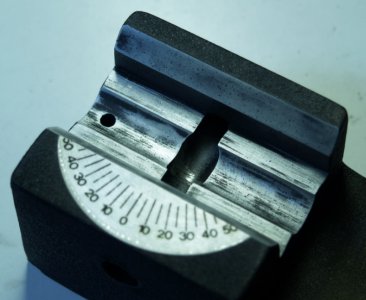
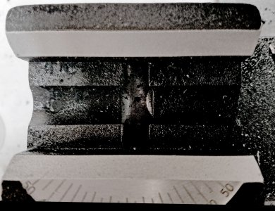
headstock end.jpg

The bed only contacts the base along the angled portion of the bed. I figured that out after removing all the paint.
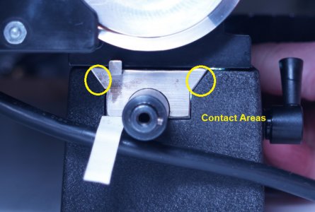
contact areas.jpg

Eric
 
Eric,

The deflection resulting from compression of the paint near the screw is consistent with the vertical direction of the headstock misalignment on my lathe.

I found your thread about the paint. In it, I posted that the base of my lathe has paint in the contact areas.

Karl
 
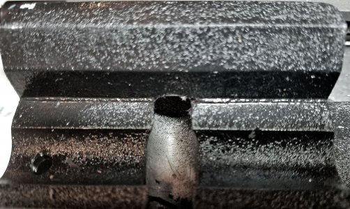
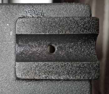
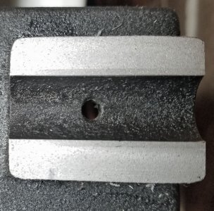
Following EricB's lead, I removed the paint from the areas of the lathe base that contact the lathe bed. The result is that vertical misalignment decreased: from 0.002,3 inch rise to 0.001,1 inch rise from left to right, along 2.75 inches of the z-axis.

Here are before and after photos of the base contact areas:
20240227_011319 base left side.jpg20240227_012436 base - paint removed from left-side contact area.jpg
left side

20240227_012506 base right side.jpg20240227_013941 base - paint removed for right-side contact area.jpg
right side

I used paper towel and acetone to rub off the paint. The paint softened significantly after being in contact with acetone-soaked paper towel for ten seconds.

Karl
 
Last edited:
Following EricB's lead, I removed the paint from the areas of the lathe base that contact the lathe bed. The result is that vertical misalignment decreased: from 0.002,3 inch rise to 0.001,1 inch rise from left to right, along 2.75 inches of the z-axis.

Karl

You might also consider mounting your lathe so that the entire length of the base is supported on a solid piece of material.

Eric
 
You might also consider mounting your lathe so that the entire length of the base is supported on a solid piece of material.

Eric
Eric,

My lathe is mounted on an 80/20 frame. I assembled the 80/20 frame with the aid of a sheet of glass, for flatness. The frame has three adjustable feet -- two along the left side and one on the right side -- for leveling the frame. To make the lathe bed level at both sides when it is mounted to the frame, I needed to include an 0.003" shim under the right, front mounting location of the lathe base. Without the shim, the bed is twisted. I don't know the cause of the twist. I want to check the flatness of the base and the bed, before I make any changes to how the lathe is mounted.

Karl
 
Last edited:
Hi Karl,

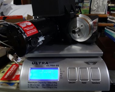
I had seen how you had mounted your lathe. It looks like you have the headstock end cantilvered off of your supports. So the headstock, motor, and speed control assembly (almost 9 pounds), along with the end of the lathe, are floating unsupported.
headstock weight.jpg

I figure if you are going through the trouble of chasing alignment it would be a good idea to start with a more rigid setup. Here's a simple test. Chuck a length of stock and place a test indicator at the end. Then just press on the headstock and observe the indicator.


Eric
 
Hi Eric,

Yes, the portion of the base-and-bed to the left of the support mounting screws cantilevers out.

I remeasured the vertical misalignment along 2.75 inches from left to right using a test bar. I got 0.001,1 inch rise, again.

I then removed the motor from the headstock, and measured again. The rise was 0.000,8 inch, or 0.000,3 inch less.

Thank you for explaining the rigidity issue.

Karl
 
Eric,

The bed is the core of the lathe. The headstock mounts to the bed, and the motor mounts to the headstock. It seems to me that if the weight of the motor causes more deflection to the bed than is acceptable to me, then I ought to relocate the motor.

From the contruction of the lathe, it appears that the base is not meant to add rigidity to the bed. The base is not directly fastened to the bed. Rather, the base is fastened to the lead screw support on the left end, and to the lead screw thrust on the right end. Based on the types of screws used, the lead screw support and the lead screw thrust are more firmly fastened to the bed than to the base.

I think that the base ought to be mounted in a manner that does not apply uneven forces where the bed contacts the base.

Yesterday, after comparing headstock spindle misalignment with and without the motor installed, I had ideas of lengthing the 80/20 frame to match the 24-inch length of the lathe base, and adding a 3-inch wide by 1-inch thick by 24-inch long aluminum bar between the 80/20 frame and the lathe base. Plans for adding the bar became difficult, though: milling the bar flat, and milling the bottom of the lathe base flat.

Karl
 
Last edited:
Back
Top