So I'm a machinist now?

So... you painted your other tools to match the Bridgeport? :)

Ha! It worked out quite well really! Shame about the knee. It actually looks like the knee might be original to the mill as the green is on top of a cream coat. Why they didn’t paint the whole thing though is another matter.

Bottom Picture, is the picture reversed, or are you threading left to right, or is it a left hand thread?

I’m threading in reverse with a LH tool. It means you thread with the lathe in reverse towards the tail stock. It means you can go right up to a shoulder with no undercut and not crash. Plus you can thread at high speed. I was threading at 300 rpm. I would have liked to have gone faster but I was using flood coolant and I was already wet enough!

A nice table on wheels in middle would be sweet. That much open space is dreamy.

Yes that’s my plan! I was thinking maybe some toolboxes on wheels which I could store in process parts on top of. Maybe even a surface plate in there too.
 
Yes that’s my plan! I was thinking maybe some toolboxes on wheels which I could store in process parts on top of. Maybe even a surface plate in there too.

I got 2 smaller tables with wheels, got them from salvage run. One has a larger arbor press, a rod Shear, ring roller, small arbor, a hole punch, anvil and a vice. tough to fit all on and have space to use. some stuff has to be higher and at times you have to unbolt tools. Never enough space. I should take a picture or 2.
 
This belies your thread title, I'd estimate that you've been a machinist for quite some time.


As much as I’d love to take some credit for the idea I stumbled on a YouTube video describing it some time ago.

I’ve actually only been machining for a couple of years but I learn pretty quickly! It helped that my last job was as an engineer in a manufacturing facility and there were a few great guys there who I could run ideas by. The one downside to leaving!
 
I’ve spent the last week finishing off a few things. I’ve brought the good camera in to the workshop to try and showcase some of the products I am making. I’ve not got a social media presence yet but I figure it’s the way to go these days. I’ve got all the accounts created and a logo but no posts as yet. Once I’ve got a load of pictures I’ll kick things off. My thinking is that I can get enough material for a post every couple of days to try and get a few followers. But in the mean time I thought I’d try and give you a sneak peak!

88D65B87-7D5A-4136-A734-0DB68115C474.jpeg

Some brass heatsinks, threaded M33 x 1.5. These are my own design to fit into the light sabre project I mentioned earlier in the thread.

67B10844-1C52-44BD-8359-6A87EC376F54.jpeg

And in the making. Getting the Bridgeport to pay for itself!

6AE4582C-D9B3-48D9-809B-0D6F1D882F34.jpeg

And the finished sabres! The chap is wanting 4 different models in his range so hopefully I’ll be seeing more of these soon! In the mean time I’m going to have to have a think about deep hole boring. I had a real hard time with chip evacuation in the bores. It’s not a huge problem for these parts but I’d still like to get this dialled. I tried a through coolant Boring bar but I don’t have sufficient coolant pressure to blast this chips out so I found aiming the flood was the most effective.

I’ve been working on a few other things as well including more parts for my first “real” customer. I’m not sure on the etiquette of posting pictures of his stuff yet so I’ll hold fire for now and ask him when doing the next batch which will hopefully be in the next couple of weeks.

My next job is to think about fixturing in the mill. The last job I ran involved 20 parts with various drilling, threading etc. Nothing too hard but it was very time consuming. I’m thinking of an aluminium plate bolted to the table that I can load a dozen or so parts into at a time. This would hugely reduce the time taken for tool and part changes which added up quite quickly! I actually made a mini version that allowed me to clamp a single piece so that I didn’t need to re find centre on the DRO each time.

C3D362B8-AA00-4FA0-8C9B-ADE9423DBA4F.jpeg

Here I could place the parts I was making in the recess and up against the edges to locate them. The 16 mm square bar was then bolted down securing the parts in place. I’m thinking a slightly more refined version in a plate capable of taking a reasonable number. It’s just whether the cost of the fixture is worth it in the long run. Something for me to ponder!
 

Attachments

  • 4D6CD464-7D01-49D5-AD57-11814EC9FACD.jpeg
    4D6CD464-7D01-49D5-AD57-11814EC9FACD.jpeg
    38.7 KB · Views: 13
  • 688C457B-06F4-4BFB-9AAD-AFE346B98FB1.jpeg
    688C457B-06F4-4BFB-9AAD-AFE346B98FB1.jpeg
    31.3 KB · Views: 13
I’ve spent the last week finishing off a few things. I’ve brought the good camera in to the workshop to try and showcase some of the products I am making. I’ve not got a social media presence yet but I figure it’s the way to go these days. I’ve got all the accounts created and a logo but no posts as yet. Once I’ve got a load of pictures I’ll kick things off. My thinking is that I can get enough material for a post every couple of days to try and get a few followers. But in the mean time I thought I’d try and give you a sneak peak!

View attachment 296055

Some brass heatsinks, threaded M33 x 1.5. These are my own design to fit into the light sabre project I mentioned earlier in the thread.

View attachment 296056

And in the making. Getting the Bridgeport to pay for itself!

View attachment 296057

And the finished sabres! The chap is wanting 4 different models in his range so hopefully I’ll be seeing more of these soon! In the mean time I’m going to have to have a think about deep hole boring. I had a real hard time with chip evacuation in the bores. It’s not a huge problem for these parts but I’d still like to get this dialled. I tried a through coolant Boring bar but I don’t have sufficient coolant pressure to blast this chips out so I found aiming the flood was the most effective.

I’ve been working on a few other things as well including more parts for my first “real” customer. I’m not sure on the etiquette of posting pictures of his stuff yet so I’ll hold fire for now and ask him when doing the next batch which will hopefully be in the next couple of weeks.

My next job is to think about fixturing in the mill. The last job I ran involved 20 parts with various drilling, threading etc. Nothing too hard but it was very time consuming. I’m thinking of an aluminium plate bolted to the table that I can load a dozen or so parts into at a time. This would hugely reduce the time taken for tool and part changes which added up quite quickly! I actually made a mini version that allowed me to clamp a single piece so that I didn’t need to re find centre on the DRO each time.

View attachment 296060

Here I could place the parts I was making in the recess and up against the edges to locate them. The 16 mm square bar was then bolted down securing the parts in place. I’m thinking a slightly more refined version in a plate capable of taking a reasonable number. It’s just whether the cost of the fixture is worth it in the long run. Something for me to ponder!
Maybe try compressed air with a throughcoolant bar when boring deep?

Sent from my LYA-L29 using Tapatalk
 
That could be worth a shot. On some pieces I tried blasting air through the spindle which had limited success. I found after a while the spindle packed with long stringy chips which rendered this method ineffective. Getting the compressed air through the boring bar might help with this. The other thing I might try is two coolant streams. One through the boring bar and the other flooding the bore.

It’s a tough one, if I increase the feed to break the chip then after a certain depth they stop clearing and cause problems. I actually found the best results by going for a slow feed and letting the chip push ahead of the cut with the resulting stringy chip being pushed all the way through the headstock. That was fine but would occasionally break and cause problems. Or they’d pack up in the spindle.

At some point I think I’m going to put a coolant pump in the Bridgeport so I might take the one from the lathe for that and put a more powerful pump with a much larger sump in the lathe. The current one if far too small which means constantly having to top it up. On the plus side it’ll never go rancid as it never lasts long enough! But then coolant on the manual lathe is already messy enough!
 
Well it's been a very busy few months! Not all of it in the shop - a lot more time than I'd anticipated gets spent in front of the PC. As such I've been lurking a little but haven't really had the time to post much on this forum. That being said, I'm now getting evenings back which is a novelty - while I was working "the day job" as soon as I was home it was dinner, kids in bed, back to work! It's nice and I definitely haven't looked back since leaving the day job!

I've still been doing the jewellery although it's something I'm wanting to do less of so I can focus on engineering work as that's what interests me the most.

Pretty much every job I've taken on has been a first for me but it's been a lot of fun learning the best ways to tackle a problem! The tooling budget is getting a bit out of hand though! :oops: I guess as I'm just starting out pretty much every job involves a new tool or inspection instrument. I've now got micrometers from 0-275 mm - way bigger than I thought I'd need! I've invested in the Insize range and I'm pretty happy with them. Sure they're not quite as silky smooth as my Mitutoyo micrometer but the accuracy is there and they're nice enough. I'll probably get Mitutoyo's in the 50-150 range when I can afford to. I'm looking forwards to using the big one on an aluminium bronze ring I'm making this week! Genuinely not sure if I can swing that without removing the gap in the lathe! It should fit but I didn't consider the additional room required for the chuck jaws (plus the only material I could find to spec was 1" oversized - I'll have fun roughing that down!). My biggest tooling purchase to date though was a Quick cut knurling tool. I've not tried it out yet but I've been itching to! I know some folk have had success making them but to be honest I've just not had the time and I doubt I'd get it spot on first go so this tool promises to be very adjustable so I can dial it in to any diameter under 250 mm which should suit all my knurling needs.

Materials wise it's mostly been steel and a lot of 4145 HT. It machines nicely but it's hard to push the machine hard enough to break a chip without it stalling. I'm screaming out for a bigger lathe so I think I'll be looking to invest in the new year. I'll probably keep the current one for second op work and general use. One can never have too many...right? In the mean time I've had some success by slowing it down and taking a bigger depth of cut or faster feed but a lot of the parts have surface finish requirements which mean I have to live with the stringy chips for the finishing passes.

That's enough of my rambling for now though - here's a few pics of various projects I've been working on:

449FBD98-0ECF-4B0C-B722-FD7D534904D4 2019-10-22 22_04_42.JPG

I enjoyed this one - first real milling job for me. This one was just EN3B steel so nice and easy to work although not always the best finish. This part was the drive shaft for a plastic shredding machine.

20190806_092218020_iOS.jpg

A little project for the neighbour - I made an adapter for our kitchen sink that this threads onto as I was getting fed up of soaking the floor every time we did a water change on the fish tank. The wife mentioned this to a couple a few doors down so I made couple of them for friends and family. I used 316 stainless as it's suitable for use in drinking water systems.

20190807_122751502_iOS.jpg

I underestimated this job a little. The job itself wasn't too bad other than, being Inconel 718 and my lathe being under powered it took a long long time to get that bore done! I've had to sign confidentiality agreements with most of my clients so no pictures of the finished parts although they were simple enough apart from a groove on the OD. Did I mention I need a bigger lathe? Ha! Rigidity, or lack thereof was the name of the game on this one! Still, got it done and managed to meet the surface finish requirements without having to resort to emery cloth which was a bonus.

20190816_103115144_iOS.jpg

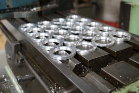
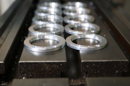
A nice little run of parts for an afternoon. Not much to these and with the exception of the smaller diameter the tolerances weren't fussy which is always nice! I had a job in recently where the engineer had gone mad with the -+ 0.001" tolerances! I managed to get a concession granted on one as it would have been impossible to measure (in my shop anyway).

20191016_115016170_iOS.jpg

It took a lot of time to get from round stock to the blank on the left! Milled it all in the Bridgeport with an 80 mm face mill. As it turns out the Bridgeport doesn't have the power to take decent cuts so it was a slow process but got there in the end. Managed to cut it closer to finish size in the band saw after putting in some bolt holes. The material specified just wasn't available in a more economical form.

20191023_103225930_iOS 1.jpg

That cut probably saved me 90 minutes if not more! Plus the inevitable broken inserts! I think I spent about £150 just on inserts roughing this job down!

20190904_131031725_iOS.jpg

Another interesting little one. Some odd ball dimensions on the reamed holes in these and I actually struggled to find a reamer to suit! Got there in the end though!

20190910_094231233_iOS.jpg

Some big boy threading going on here! A 3-1/2" 6TPI modified STUB ACME thread - this part was actually just a trial for a job I was quoting. I genuinely wasn't sure if the lathe would handle it without chattering itself apart! Turned out pretty nicely though. I ended up getting the job but it's in 4145 HT so I'll no doubt have fun when the time comes! I've currently got the material cut and sat on a pallet next to the machine - just need thread gauges before I can proceed with the job!

20191007_130407037_iOS.jpg

A job I've got coming up requires etching the part numbers on. I could vibro etch (and I know a lot of the other local shops do this) but I want my parts to stand out so I decided to build a DIY electrochemical etching unit. You can buy them commercially but they're expensive and, as I mentioned earlier - my tooling budget has already been decimated! Still, with bit of research and repurposing bench top power supply I already had I've been able to get pretty good results. The top was the first attempt which didn't go as well as I'd hoped. A quick play about and I ended up with the second one and I was pretty pleased with it. The text is crisp and clear and the etching doesn't rub off. I reversed the polarity for a bit which removes metal before switching back to redeposit and darken. The proper systems use AC power to do this but my power supply only does DC but still, the results were good.

20190922_043440036_iOS.jpg

And finally (for now at least - this post is already quite long!) I've had a few jobs machining rubber lately. I've been finding rubber all over the shop for weeks now! The picture above was taken after one part - I had 20 to do! I did not enjoy the clean up! It got tangled around the feed screw causing it to bind up - luckily I managed to pull enough out without having to resort to removing the feed screw! All the handwheels had to come off though. If I'm honest it was an utter pain of a job - they managed to get me own quite substantially on price. I still made reasonable money on the job but I think in future rubber jobs are going to incur a hefty clean-up surcharge!

I hope you've all enjoyed the read! :faint:
 
Saml, I have that same lathe, though mine is badged Kent KLS-1340A. On the front it says KENT USA. On the back, on a small and partially hidden tag it says "Made in China." Gray instead of green. Still, pretty nice lathe for what I use it for. Yours does look like it might be narrower (shorter bed) so maybe it is a 13x30 (?) Mine measures 55" from the right side of the headstock to the end of the ways.
1572305496151.png
 
Whats the purpose for clamping your part into a small 3 jaw chuck that is then clamped into a larger 3 jaw chuck? Looking at the picture the part looks like it would have fit into the larger 3 jaw without needing the smaller chuck and neither of those 2 chucks appear to be adjustable like a Buck Adjust-Tru type of chuck to help with the run out which adds to the confusion.
 
Back
Top