- Joined
- May 27, 2016
- Messages
- 3,477
A switch for a lathe electric motor is not like a switch for a light bulb, or hair drier.Pretty sure Blk & Red is one direction and Blk and Yel the other direction. I'm going to gut the switch assembly can and put a double pole double throw toggle switch in it's place.
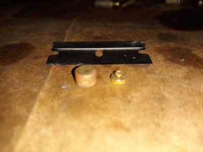
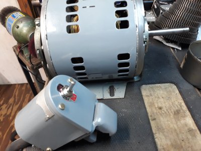
There is a reason the original switch (picture 20191220_160737) is built like it is.
The square-rod cam switch with robust terminals is what it takes to survive the attempts to switch on AND, off, with the switch off action being the more difficult for the switch.
I did not really want to get so expansive, but I think we need to say this stuff. You cannot be casual about the switching!
What really happens
When the motor is running, it is also generating it's own voltage in opposition to the mains supply connected to it, and the house power supply is the winner! The motor rolls forward, and the real volts that drives it is the difference between the supply volts, and the motor-generated volts, which is also known as "back-emf". When you switch off, the back emf arc that happens as the switch contacts part can splat them into a pitted mess!
When you switch on, the motor is momentarily stalled, with no back emf being generated. The forward current surge is several times the normal current. The only thing limiting it is the (low) resistance of the copper coils, and briefly, their inductance. The inductance limits the transient current, but works against you when you switch off, as the stored (magnetic) energy comes out. In some motors, the switch-on surge can be 10x or 15x the rated current, which is why industrial-use trip-switches have grades which allow a surge for a limited number of milliseconds.
If you just switch off, you have to wait for the lathe to roll to a halt by friction, or use some kind of brake. Some switching arrangements change over from supply to resistive load, which takes a pulse of heat as it (electrically) brakes the motion. These can come to a speedy stop. Don't be tempted to switch away from power into a short-circuit load.The sudden stop can break things! Choosing the right dump resistor can let you have the motor roll to a sweet stop.
Some motors have more centrifugal switching built into them, which takes care of the run-up, and run-down. They switch out of the way when the motor gets to a threshold speed. These can sometimes mess up attempts to use a VFD unless you knew everything about your motor from the beginning.
A traditional way, (other than using mighty contacts), is to use a small relay contactor, which is built to take it, and to go further, using a two push-button scheme for a latching relay stop-start, with the stop pushbutton in series with a big red emergency stop knob. Ready-wired versions of these are easy to find on eBay, Amazon, etc..
Solid State Switching
Given the very low cost, and the effectiveness, I like to use solid-state semiconductor switching. You can get a 280Volt 40A relay for less than 10 bucks. This banishes all sparking, arcing, and they cannot wear out. With one of these, you can use a light-duty switch like the one you posted the picture of. That switch would be used to operate the control input terminals of the SSR, (usually numbered 3, and 4) The main motor current goes through the output terminals (usually numbered 1, and 2). The neutral is not switched, except at the main isolator switch upstream, which you should have.
These isolators also do not cost the Earth, and a favourite style is a "rotate through 90°" type, but you can use what you like
Here --> LINK
Select with care. AC throughput uses TRIAC semiconductors, which can be controlled by either low voltage (3V to 36V DC) OR low voltage (4V to 36C AC, often 24V AC) OR by full mains voltage (like 97VAC through 280VAC). To take 1/2HP energy out of a house supply, a norm in USA is two 110V or 120V live lines with a common neutral, intended for higher energy stuff like cookers, etc.
If the motor is a 240V version, then you need to switch BOTH the lives, and be very careful, and fully knowledgeable about exactly how the motor is to be wired up. Again, I could not know sufficient details from the pictures, so I just guess. With a single phase motor, it should be easy enough.
Conveniently, you could get a SSR for a 3-phase, and just use two of the switches, ignoring the third. Don't be shy about using a 40A or 60A SSR relay for a motor that might take only 2A or 3A when running. If you do use a relay contactor, you would choose one with the right kW rating for AC motor use. Likely, even the lowest rated would be more than your lathe motor needs.
If you want to, you can use a small, low power latching relay, with "stop" and "start" buttons, so long as there is the SSR on the end if it all, doing the main current switching. You can also get kit where everything is solid state, including the latching and stop functions.
From UK - but I am sure you can find others.
Here is an isolation switch --> LINK#2
OR --> LINK#3
You don't use it to stop and start the lathe! You can find others, but the types with the ready-made enclosure box cost a few bucks more.
Getting fancy
These days you can find semiconductor controlled "soft-start" switches. My woodworking chop-saw comes with that feature built in, but you can get separate kit that does this. It gets over the violent jerk start, and the high surge current.
For a small lathe, with (say) a 1/2HP motor, you do not need mighty industrial type contactors, but I think you perhaps do need a little more than the small duty switch you proposed to use, especially compared to the one that was there originally.
Get a picture of the motor rating label. It can help. Remember that a 1400W hair drier does not need a heavy duty switch, because the heaters are resistive, They do not store magnetic energy. A 700W squirrel-cage induction motor is a different situation altogether.
Last edited: