- Joined
- Jan 3, 2016
- Messages
- 11
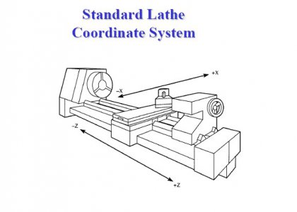
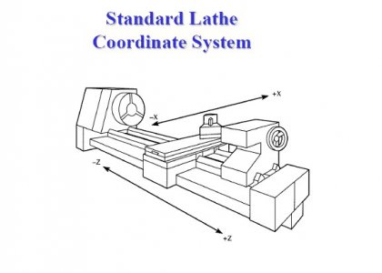
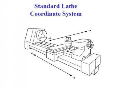
I'm really new at this hobby (first posting, first attempt to learn rather than maim) and am setting up igaging scales for my shoptask. I'm trying to teach myself to think in gcodes from the beginning and so am trying to set my DRO scales to mimic the conventions of CNC, which I understand describes everything in terms of tool motion. I found the following to describe translations of the tool in terms of coordinate system (haven't found the convention to describe rotation as plus/minus forward/backward yet). I'd appreciate a read to see if I have this right before I start drilling holes and chopping up my new gauges.
There was a long thread that described MILL motion, that in its most succinct form led to this summary:
X+ - table moves left/west
Y+ - Table moves away from you/North
Z+ - Tool moves up/into spindle.
From the perspective of the operator standing afore the machine:
X+ Tool movement to right of operator (Table moves Left)
Y+ Tool moves toward operator (Table moves away)
Z+ Tool moves up/into spindle, away from the work.
The Y axis has me a bit confused. This would put the origin of a tool path in the upper left corner of a sheet of graph paper. (This is common in computer graphics but uncommon in mapping, at least in the northern hemisphere!)
I grabbed this from a professor in Ireland, it seems consistent with the convention that I was familiar with:
http://derek.dkit.ie/graphics/vectorMathematics/vectorMathematics.html
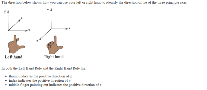
So, from the perspective of both the tool and the operator, both for the lathe and the mill, the LEFT HAND hand rule is what describes tool motion. I aim my left index finger towards me (postive tool motion toward the operator is plus Y), my thumb points to the right (positive tool movement to the right is plus X) , and index finger points upward (positive tool movement is into the spindle of the mill).
(This is convenient cuz I am right handed and can write something down while I am struggling with pointing a finger at myself.)
SO HERE IS MY QUESTION: I THINK THIS MEANS THAT THE ZERO OF MY IGAGING SETUP SCALES SHOULD BE LOCATED AS FOLLOWS:
X - SCALE ZERO NEAREST THE SPINDLE, measuring tool motion along the bed (tool movement is toward tailstock of lathe, scale numbers increase in that direction). The rule would be mounted facing the operator, on the bed closest to the operator, and the operator would see the scale legends with Zero to the far left.
Y - SCALE ZERO FURTHEST AWAY FROM OPERATOR, measuring tool motion along the cross slide, with plus motion and increasing scale reading moving the cross slide table away from the operator. If the operator is standing at the left end of the bed, looking over the spindle, the scale would be mounted on the cross slide closest to the spindle, the scale legend visible, with the zero of the scale to the observer's left. The zero of the scale would be furthest from the operator position.
Z - SCALE ZERO AT THE BOTTOM OF QUILL TRAVEL , so that as the tool moves upward, and the quill retracts into the head, the numbers of the scales get larger. The zero of the scale is closest to the floor, and as the quill moves upward the scale readings increase.
IS THIS HOW YOU SET UP YOUR COORDINATE SYSTEM? ANY TIPS ON UNDERSTANDING TOOL DIRECTION CONVENTION?
Thanks for reading yet another rambling post from yet another noob.
Joe
There was a long thread that described MILL motion, that in its most succinct form led to this summary:
X+ - table moves left/west
Y+ - Table moves away from you/North
Z+ - Tool moves up/into spindle.
From the perspective of the operator standing afore the machine:
X+ Tool movement to right of operator (Table moves Left)
Y+ Tool moves toward operator (Table moves away)
Z+ Tool moves up/into spindle, away from the work.
The Y axis has me a bit confused. This would put the origin of a tool path in the upper left corner of a sheet of graph paper. (This is common in computer graphics but uncommon in mapping, at least in the northern hemisphere!)
I grabbed this from a professor in Ireland, it seems consistent with the convention that I was familiar with:
http://derek.dkit.ie/graphics/vectorMathematics/vectorMathematics.html

So, from the perspective of both the tool and the operator, both for the lathe and the mill, the LEFT HAND hand rule is what describes tool motion. I aim my left index finger towards me (postive tool motion toward the operator is plus Y), my thumb points to the right (positive tool movement to the right is plus X) , and index finger points upward (positive tool movement is into the spindle of the mill).
(This is convenient cuz I am right handed and can write something down while I am struggling with pointing a finger at myself.)
SO HERE IS MY QUESTION: I THINK THIS MEANS THAT THE ZERO OF MY IGAGING SETUP SCALES SHOULD BE LOCATED AS FOLLOWS:
X - SCALE ZERO NEAREST THE SPINDLE, measuring tool motion along the bed (tool movement is toward tailstock of lathe, scale numbers increase in that direction). The rule would be mounted facing the operator, on the bed closest to the operator, and the operator would see the scale legends with Zero to the far left.
Y - SCALE ZERO FURTHEST AWAY FROM OPERATOR, measuring tool motion along the cross slide, with plus motion and increasing scale reading moving the cross slide table away from the operator. If the operator is standing at the left end of the bed, looking over the spindle, the scale would be mounted on the cross slide closest to the spindle, the scale legend visible, with the zero of the scale to the observer's left. The zero of the scale would be furthest from the operator position.
Z - SCALE ZERO AT THE BOTTOM OF QUILL TRAVEL , so that as the tool moves upward, and the quill retracts into the head, the numbers of the scales get larger. The zero of the scale is closest to the floor, and as the quill moves upward the scale readings increase.
IS THIS HOW YOU SET UP YOUR COORDINATE SYSTEM? ANY TIPS ON UNDERSTANDING TOOL DIRECTION CONVENTION?
Thanks for reading yet another rambling post from yet another noob.
Joe


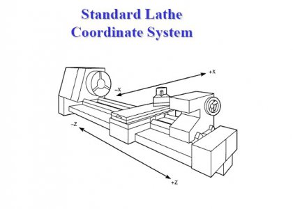
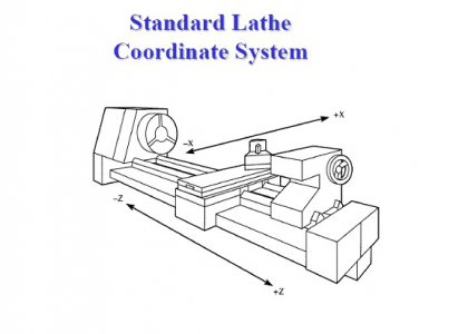
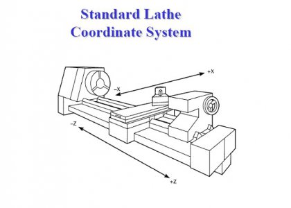


 I can only think in terms of table movement for the X and Y axis because that's what I see moving when I run the machine.