Stepper control packaging

kmanuele

H-M Supporter - Diamond Member
H-M Lifetime Diamond Member
Joined
Jan 25, 2022
Messages
110
I installed a stepper motor on the Z-axis of my mill (PM728), and finally got the code sorted out.

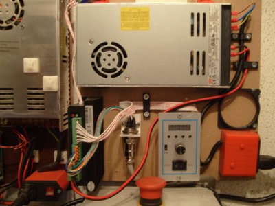
Next: optimize (minimize) packaging of the controls. Initial config in the photo. The driver is a DM860I, which sticks up there like a sore thumb, but I need its voltage/current ratings for the motor and it only mounts vertically like that.

Cooling isn't really an issue, as this is very intermittent duty (I took the fan out of the PS because of noise).

The PS can be mounted on edge, making narrower but still tall arrangement. Maybe the only real option?

Ideas, comments ??

thanks
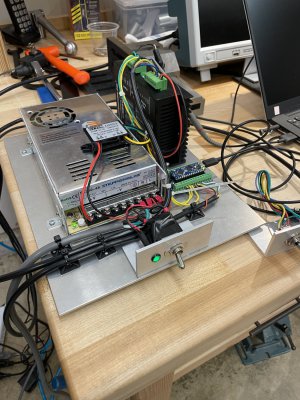

IMG_4373.jpg
 
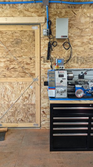
I put a similar setup in a Altronix power supply box from a defunct camera system that i had:

PXL_20230408_204044807(1).jpg
 
Last edited:
I installed a stepper motor on the Z-axis of my mill (PM728), and finally got the code sorted out.

Next: optimize (minimize) packaging of the controls. Initial config in the photo. The driver is a DM860I, which sticks up there like a sore thumb, but I need its voltage/current ratings for the motor and it only mounts vertically like that.

Cooling isn't really an issue, as this is very intermittent duty (I took the fan out of the PS because of noise).

The PS can be mounted on edge, making narrower but still tall arrangement. Maybe the only real option?

Ideas, comments ??

thanks


View attachment 446682
You can either make your stuff look fancy or make it invisible. If you were to mount that stuff in a toolbox and throw it under the table, there wouldn't be a big obnoxious electrical enclosure conspicuously mounted on a wall somewhere. There would just be a toolbox, under the table, right where anyone would expect a toolbox to be.
 
You can either make your stuff look fancy or make it invisible. If you were to mount that stuff in a toolbox and throw it under the table, there wouldn't be a big obnoxious electrical enclosure conspicuously mounted on a wall somewhere. There would just be a toolbox, under the table, right where anyone would expect a toolbox to be.

Invisible is ok. I've considered putting it inside the base of the mill, which has easy access. It would require several holes and gland nuts for cable entry, but still an option.
 
Thanks for the compliments. I'll try to get a pic of the inside of the box later tonight. I plan on using gland nuts but so far i've only used wire loom temporarily - we'll see how permanent that is! :) The main reason i used the box i did is b/c i didn't want to spend money on a box when i had one that i could make work. It meant that i had to get a little creative on how i mounted things but the way i mounted it is almost like how @kmanuele has it now.
 
It looks OK to me but:
  • use shrink tube on all soldered connections.
  • use a ferrule (isolated) on all other wires.
  • keep the stepper control signals away from the power/motor/mains cables.
  • the aluminum plate should be connected to the mains earth using a crew and a toothed washer. Better sure than sorry
I use connectors to connect steppers, limit switches, mains supply, etc. My mains supply/switch (euro connector) has a fuse, light to signal mains is on and a double pole switch to make sure both high voltage lines are disconnected.
S7300757.JPG
 
Thanks for the compliments. I'll try to get a pic of the inside of the box later tonight. I plan on using gland nuts but so far i've only used wire loom temporarily - we'll see how permanent that is! :) The main reason i used the box i did is b/c i didn't want to spend money on a box when i had one that i could make work. It meant that i had to get a little creative on how i mounted things but the way i mounted it is almost like how @kmanuele has it now.

I am always leery of closed boxes for power-consuming equipment. Though in my case, likely not a problem as the equipment is at idle most of the time.
It looks OK to me but:
  • use shrink tube on all soldered connections.
  • use a ferrule (isolated) on all other wires.
  • keep the stepper control signals away from the power/motor/mains cables.
  • the aluminum plate should be connected to the mains earth using a crew and a toothed washer. Better sure than sorry
I use connectors to connect steppers, limit switches, mains supply, etc. My mains supply/switch (euro connector) has a fuse, light to signal mains is on and a double pole switch to make sure both high voltage lines are disconnected.
View attachment 446804

Agree. Final config will have a hard ground at the plate. Connectors are at the motor and control switch sides. Stranded wires into clamp terminals are pre-soldered. Not a big fan of ferrules -- a subject of debate back in the 80s in my business.

Thanks
 
Back
Top