Tachometers with hall proximity sensor question

Suzuki4evr

Registered
Registered
Joined
Sep 29, 2017
Messages
2,251
Hallo guys and girls

I have a question about these cheap
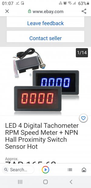
LED 4 Digital Tachometer RPM Speed Meter + NPN Hall Proximity Switch Sensor.​

Screenshot_20210613-010732.jpg
I understand that you need to place the magnet on the spindle or somewhere and place the sensor over the magnet,but my question is this. Say I place the magnet on the the driven step pulley,which have 4 pulleys which can be used, does it matter on which pulley you place it to achieve the correct rpm reading if my belts is set to reach 1300 max rpm at the moment? I am asking because we now the bigger the OD od the pulley,the faster that magnet is going to come past that sensor which will effect the rpm reading......right? I hope I explained it ok. I can't place the magnet directly on the spindle.

Thoughts please
Michael.
 
It does not make any difference, they will all read the same. The sensor is magnet polarity specific, so it only works properly when you have the correct magnet polarity triggering the sensor. You can power everything up and run the magnet across the sensor with your hand, the correct polarity will trigger the sensor light. I mark the magnet so when you attach it you have the correct orientation. Often I will use a smaller neodymium magnet then the larger one they usually supply.
 
Everything mksj said. Will just add that the diameter effects the speed going past the sensor yes, but that does not affect the RPM. It will still only go past the sensor 1 time per revolution. When you put a 1/8” end mill in your machine and spin it 1300 RPM that is only 43 surface feet per minute (SFM) put a 3” face mill in there at 1300 RPM and you will be cutting at 1022 SFM but spindle is still only going 1300 RPM. Hope that helps.
 
Last edited:
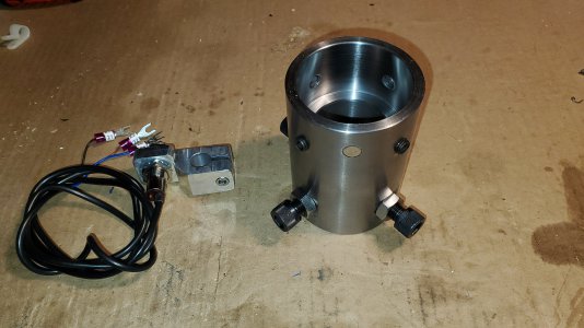
Ok so in conclusion, I can put the magnet(which they supplied) on any of the 4 pulley faces that will allow me to fit the sensor in the mill pulley cavity/compartment/housing or whatever you want to call it?
 
When the magnet goes pass the Hall effect, the Hall produces an electrical spike. Then your tach counts the number of spikes in a certain time. Example: 100 spikes in a minute equals 100 RPM. Think of it this way. The magnet is like a one tooth gear. When it turns one full turn, it will turn another gear one step. 100 Steps in a minute is 100RPM. The diameter of the one tooth gear makes no difference.
 
When the magnet goes pass the Hall effect, the Hall produces an electrical spike. Then your tach counts the number of spikes in a certain time. Example: 100 spikes in a minute equals 100 RPM. Think of it this way. The magnet is like a one tooth gear. When it turns one full turn, it will turn another gear one step. 100 Steps in a minute is 100RPM. The diameter of the one tooth gear makes no difference.
Thanks. Good explanation.
 
Never heard of these Hall effect units until coming to my current position . We have them everywhere . All of ours uses a disk with different amounts of magnets that mount directly on the motors output shaft . The ring mounts in between the motor and gearbox . Once in a while , the electricians will grab the wrong disc and we have issues . :big grin: Had to swap out a blown motor last night with one of these mounted on it . Putting it all together was fine , lifting it and getting it back into the line was a nightmare as always .
 
Think of the "Hall Effect" device as a really fast limit switch, with the magnet being the operator. I must "assume" the pulley in question is a stack, moving the belt one to another to change speed. As long as the magnet rotates the same speed as the spindle it's soup. It only gets confusing when the magnet is on an idler or the driving pulley.

There are some games you can play with the "Hall" sensor. Two magnets will show twice the speed. It wouldn't be a good idea on machine tools, but to mess with someone's mind. . .

.
 
Back
Top