I do not fully understand why you are not getting a reading. It could be a number of things. I do not know what model sensor or display you have, but if you got any specs with it check see what power supply voltage each wants and how much current do they need. It probably wants 12 or larger volts and >50mA or so, but there are a lot of different models on the market. I think you said you could get it to work by hand, but did not say if all the other VFD electronics were running orhow much power they might be taking. They might need the current and so there was not enough left for the Hall sensor electronics and the display. I have a little digital 5 digit panel volt meter and the display itself needs about 15mA and it varies a bit depending upon what number is being displayed. It wants to see 12 Vdc, not 24. My Hall meter/display will accept higher voltages but I just give it some of the same 12Vdc. You can purchase a small 12 Volt by 1 Amp supply for about $20 on Amazon. search Amazon with "MEAN-WELL-MDR-20-12-DIN-Rail-Supply". Anyway, test it again by hand and make sure it is not burned out.
There is a second approach you can use for the supply if the VFD has plenty of power, but I still prefer the external supply. They are cheap and easy to replace if something goes wrong and you burn it up. The VFDs are a lot more money and if the supply dies perhaps it is then useless. So the other approach is to use the VFDs 24 volt and drop it down to 12 volt with an integrated circuit three termail voltage regulator. google "LM312 voltage regulator" and you can see them and specs. Butthis will require a little circuit board and wiring on your part. The DIN supply is much quicker. In my Lathe VFD conversion I used a 24V DIN supply to power a the control circuits and took it down to 12 with an LM312 for the displays and sensor.
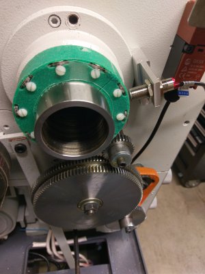
With respect to the magnet, mine are Neo magnets (neodymium, iron and boron to form the Nd2Fe14B, at ~> 30 mega-gauss-oersted energy product) at about 12mm dia and about 2-3mm thickness. I built a ring out of 1 inch thick Nylon that I had laying around. I milled a do-nut shape and then milled a slot in the flat face as near to the outer edge as possible and slipped the magnets into the slots. No glue required but I did put a small plastic screw in so that the head just lies on the milled hole. The magnet is trapped. You could cover it and then no magnetic particles would ever reach the magnet and wiping any off the nylon would be easy. Position the Hall sensor end as close to the magnet as possible. These magnets are usually oriented North and south across the thickness of the coin shape. So the sensor end faces the flat surface of the magnet. Yes, get it off the steel will increase the signal as the field will be stronger farther out from the magnet. I figure the field is maybe 50% stronger with the gap from the steel. (my holder slides onto my lathe spindle.) There Neo magnets which are oriented across the width, usually rectangular. I have some that are about 1"x1.5"x .25. These are very strong and really much bigger than needed for Hall sensing. Aliexpress has lots of Neo magnets for sale for little money. Any orientation will work. It all about getting a field at the sensor going axially down the sensor. Anyway, spacing of the sensor from the magnet is the key. Kept it small or get a bigger field. It is also good to keep the field edge sharp so that the hall signal to the hall sensor electronics is sharp (on and off the field). I will stick a drawing and a picture of my magnets, holder, and sensor mount up. I had lots of room. I made the holder extra large in OD so that I could come back and cut the inner diameter out so that I could reattach it later to a spider which is yet to be made. The do-nut /hockey puck design is thicker than need be, but I used a nylon bold in the back half to squeeze down on the spindle. I turned the ID to fit the spindle and after drilling an taping for the squeeze bolt I cut the through one side of the puck so that the bolt could squeeze the diameter.
Oh I almost forgot. I put a little wire with insulation around the magnets to fill the edges of the slots so that the magnets remained centered in their holes.
You can make a the holder out of almost anything non-magnetic (Nylon, Teflon, etc, Al, brass, etc.) , but to avoid Eddy currents, it is better if it is not metallic. You could even 3D print one. I have a friend who 3d printed a spline wrench!
Glad to help if I can. Just ask.
Dave L.