TEMCO phase converter installation - electrical assistance appreciated

E

ecdez

Forum Guest
Register Today
I picked up a TEMCO phase converter a few months ago and am finally getting around to installing it.

Here's the first issue I noticed and thus my first question.

If you look at page 5 in the instruction manual (http://attachments.temcoindustrialpower.com/Data_sheet/XR11_Data_Sheet.pdf) it shows that the single phase side is grounded but the 3 phase side is not. I've read a few things that say that 3 phase is not required to be grounded. OK, fine. I look at my machines though and they have plugs with 4 prongs. What's a guy to do?
 
You should bond together the incoming ground, the ground on the Temco unit, and the machine ground connections to form a common ground point.
 
I was thinking it had to be grounded, it just didn't make sense to me for it not to be. That said, I'm a experienced novice with electrical wiring and a total virgin at 3-phase.

Thanks for the response.
 
I picked up a TEMCO phase converter a few months ago and am finally getting around to installing it.

Here's the first issue I noticed and thus my first question.

If you look at page 5 in the instruction manual (http://attachments.temcoindustrialpower.com/Data_sheet/XR11_Data_Sheet.pdf) it shows that the single phase side is grounded but the 3 phase side is not. I've read a few things that say that 3 phase is not required to be grounded. OK, fine. I look at my machines though and they have plugs with 4 prongs. What's a guy to do?

They mean that none of the three phase conductors (T1, T2, T3) are normally grounded. The fourth prong on your plugs is for the non-current-carrying "green wire" safety ground that connects to the frames of the machines.

The ground symbols in that drawing represent the safety ground for the non-current-carrying metal parts of the system. They do not connect to any current-carrying conductors.
 
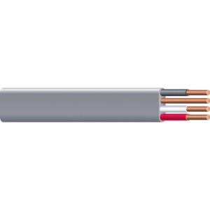
So from the receptacle to the converter I should be using wire like below, 3 hots and one ground.

I believe the tag on the RPC says 4g min for incoming power (box to RPC) and 8g min for OUTGOING (RPC to machine)

032886266669.jpg

032886266669.jpg
 
So from the receptacle to the converter I should be using wire like below, 3 hots and one ground.

I believe the tag on the RPC says 4g min for incoming power (box to RPC) and 8g min for OUTGOING (RPC to machine)

View attachment 77529

Color all exposed portions of the white wire black with a Magic Marker so that it will not be mistaken for a neutral in the future. Also clearly mark the receptacle "THREE PHASE".
 
I use a Temco RPC also for a lathe in my shop. I'm glad you enclosed a link showing the wiring to the RPC; the drawing actually shows the safety disconnect switch housing grounded as Mr. Hasler indicated. It never hurts to ask!
 
I hear they're good unit. Are you pleased with yours?


I saw the safety switch was grounded but my confusion lied at the other end, where the machine would be. The drawing doesn't show a ground coming from there. Maybe because they don't show a machine, just another switch.


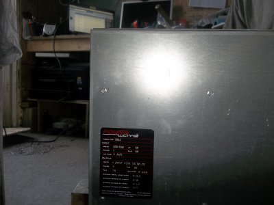
So I'm digging into this further and have come up with another question. Hopefully this will help someone else in the future who may have a similar issue. The motor has this label on it.

100_0738.JPG

If you zoom in you can see that it says under input "min wire 4 agw"
It also says under output "min wire 8 agw"


When I look in the manual that I linked in the original post on page 3 it says;
"recommended 1-Phase (input) wire size - 8 agw"
"recommended 3-Phase (output) wire size - based on load requirement"

That's a big discrepency on the input side between 4awg and 8 awg. Any ideas why? I called and asked a question today about something else and the response was less than helpful.


So I did a little math based on the guidelines in the manual. The largest machine I have is rated at 13.7 amps @ 220 volts. 13.7 * 1.732 (from the manual) gives me 23.73 amps on the single phase side. There's a built in overload of 32 amps also. From what I've read, 8g should be good to 40 amps. Am I wrong in this?

100_0738.JPG
 
I hear they're good unit. Are you pleased with yours?


I saw the safety switch was grounded but my confusion lied at the other end, where the machine would be. The drawing doesn't show a ground coming from there. Maybe because they don't show a machine, just another switch.


So I'm digging into this further and have come up with another question. Hopefully this will help someone else in the future who may have a similar issue. The motor has this label on it.


If you zoom in you can see that it says under input "min wire 4 agw"
It also says under output "min wire 8 agw"


When I look in the manual that I linked in the original post on page 3 it says;
"recommended 1-Phase (input) wire size - 8 agw"
"recommended 3-Phase (output) wire size - based on load requirement"

That's a big discrepency on the input side between 4awg and 8 awg. Any ideas why? I called and asked a question today about something else and the response was less than helpful.


So I did a little math based on the guidelines in the manual. The largest machine I have is rated at 13.7 amps @ 220 volts. 13.7 * 1.732 (from the manual) gives me 23.73 amps on the single phase side. There's a built in overload of 32 amps also. From what I've read, 8g should be good to 40 amps. Am I wrong in this?

You would need 4G if you were going to run the thing at its full load rating of 66A, but you aren't. The wire size on the input side should be adequate for the rating of the circuit breaker it is fed from. If you feed it from a 40A breaker 8G will be ok.
 
You would need 4G if you were going to run the thing at its full load rating of 66A, but you aren't. The wire size on the input side should be adequate for the rating of the circuit breaker it is fed from. If you feed it from a 40A breaker 8G will be ok.


Thanks for all your input. I'd still be scratching my head.

Since it's 220v in would it be a dual 40 breaker or a dual 20?
 
Back
Top