The Giant Binocular

Savarin- you, sir are a magician!

Or at least one of our membership who makes the most of the least!
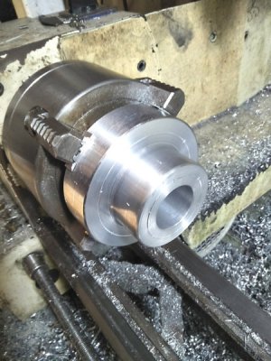
 
Some caveats for the above.
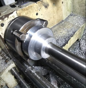
The tool did not go straight in, it wandered a bit. I found that moving the carriage back and forth a teensie amount kept it cutting reasonably on track.
The second chunk (rhs in photo) I experimented with that dangerous method of using the hacksaw in the lathe whilst it was turning. It worked very well and by angling the blade first to one side then the other whilst sawing kept it moving easily. Imaging sawing an "X" in the metal, thats why you can see all the saw marks on the face of the second cut.
I was getting ready for it to grab but it didnt.
 
Finished one altitude side boss today, bored to a tight slip fit on the shaft.

side-boss-3.jpg
side-boss-4.jpg
I've also indexed where I want to drill the holes using my simple indexer.
side-boss-5.jpg

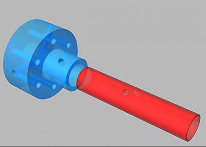
I'm going to hold it in place with two sets of three grub screws with tapered tips equi spaced around the shaft tightened into tapered holes.
But
I dont know whats best ie both grub screws in lateral alignment or the second set rotated by 60 degrees as shown on the blue part.

altitude-boss2.jpg

Any thoughts anyone???????
 
Last edited:
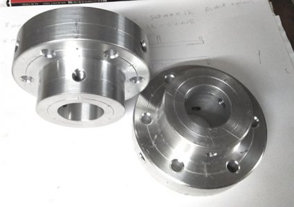
Both side bosses drilled and tapped.
I have elected to go the staggered fixing.
An interesting point was where I used the gun tap I found the bolt was a bit sloppy but with the conventional tap it was perfect.
So the three deep holes in the edge of the large diameter were started with the gun tap and the last half inch of thread cut with the conventional taper tap.
The bolt now screws in easily till the last bit whereupon it tightens up to a good fit.
side-boss-6.jpg
I have decided to use bolts to fit the bosses to the plates, its very hot and humid here so twelve long threads were placed in the too hard basket.
 
Just remember, when you get this thing all done, and you guys have your next eclipse over there, don't look right at the sun. You'll look kinda funny with 2 charred holes on the back of your head. o_O ((LOL...)...
 
I just found (and read) this thread.

Great project and execution,

Where can I get one of those magic cutoff blades? . . . Never mind. Too scary for me.

I'm subscribed.
 
I just found (and read) this thread.

Great project and execution,

Where can I get one of those magic cutoff blades? . . . Never mind. Too scary for me.

I'm subscribed.

Many thanks.
The cut off blades are the thin "T" section ones, a bit more expensive than the flat ones but I'm starting to swear by them.
 
Although I am nowhere close to this part I have been giving it a lot of thought.

mirror.jpg
The original concept and article specified "Scotch Weld Urethane Adhesive 3549" from 3M Corp.
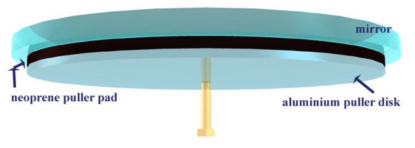
This is a two pack flexible adhesive that will be used to glue a pad of neoprene to the back face of the mirror then the aluminium puller disk is glued to the back of the neoprene pad. It was specified because it was slow to cure and being a chemical cure there would be no uncured voids between the parts.
The Scotch weld is expensive and unavailable in Australia although Gator has offered to send me some.
The main component of the flexible puller system is the neoprene pad. The glass and aluminium parts are solid and do not bend in the context of this exercise.
As this is the case then I believe I can use a slow cure epoxy adhesive such as araldite as even though it will set as a solid I am thinking that it would just be an extension of the solid glass and aluminium and shouldnt cause a problem assuming there are no drips on the edges of the glass or neoprene as there will still be the same amount of flexible neoprene to even out the pull. I will test some to check it will actually "stick
' fast' to the neoprene.
Can anyone see a flaw in my thinking?
 
I'm doubtful epoxy will stick to neoprene well. As you say, experiment first.
Robert
 
Back
Top