

-
Welcome back Guest! Did you know you can mentor other members here at H-M? If not, please check out our Relaunch of Hobby Machinist Mentoring Program!
You are using an out of date browser. It may not display this or other websites correctly.
You should upgrade or use an alternative browser.
You should upgrade or use an alternative browser.
The life of an old mill(K&T 2HL)
- Thread starter MrCrankyface
- Start date
- Joined
- Nov 7, 2019
- Messages
- 434
Thanks!Great work! I’m considering going down the same path potentially. How intense would the ball screw conversion be? That’s one of the issues that gives me pause.
I haven't landed there yet but I it will definitely require modification of both sideplates and somehow making space for the nut inside the saddle for the X axis.
Y axis should be simpler, bolt a plate with the bearings to the front and shove it through like the old one.
Z I haven't yet started thinking about and don't really know how it looks in there.
Will definitely update once I get there.

Hopefully I can start working on it in a few weeks.
Last edited:
- Joined
- Nov 7, 2019
- Messages
- 434
I'm such a scatter brain. Took me until today to realise I forgot to post part 3, which by now is old but if anyone likes watching youtube, here's the video.
- Joined
- Nov 7, 2019
- Messages
- 434
I've been giving this a fair bit of thought before arriving at this solution...
I realized going with a 1:5 ratio or larger would need a really large second pulley, or gearboxes, or a 2 stage gearing.
I really like the idea of doing the gearing in one single stage, without gearboxes.
This limits complexity which should keep down losses and points of failure.
However, a large pulley is hard to find and quite expensive.
So what I'm going to try is having an aluminium hub of sorts, which I can bolt different 3D-printed pulleys on!
After spending quite a few hours trying to model up a pulley in CAD, I think I got it nailed down!
The belt matches the 192 tooth pulley pretty much perfectly all around!

I started with a 104mm cylinder of aluminium and made this hub, the DRO on the mill helped me locate all the holes for bolts which then got drilled, chamfered and threaded.
And yes, I know my lathe needs a deep cleaning.


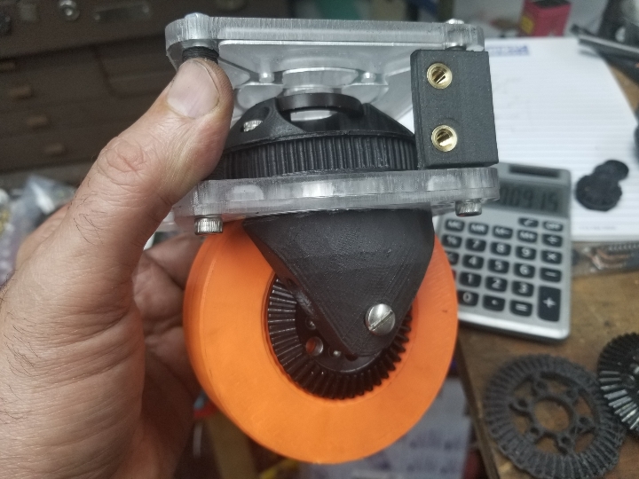
A quick prototype print was then used to verify that the hub of the 192 tooth pulley will fit on the hub.
The pulley itself is a very snug fit on the shaft of the mill, hence why I've barely put it on.
I'm both afraid and hoping it's not going to move anywhere once I push it all the way in.

Currently printing the "real" pulley, a 18 hour long print.
I suspect I will have to redesign the Y unit to the right as well since the Z gear will probably collide with some parts of it.
I realized going with a 1:5 ratio or larger would need a really large second pulley, or gearboxes, or a 2 stage gearing.
I really like the idea of doing the gearing in one single stage, without gearboxes.
This limits complexity which should keep down losses and points of failure.
However, a large pulley is hard to find and quite expensive.
So what I'm going to try is having an aluminium hub of sorts, which I can bolt different 3D-printed pulleys on!
After spending quite a few hours trying to model up a pulley in CAD, I think I got it nailed down!
The belt matches the 192 tooth pulley pretty much perfectly all around!
I started with a 104mm cylinder of aluminium and made this hub, the DRO on the mill helped me locate all the holes for bolts which then got drilled, chamfered and threaded.
And yes, I know my lathe needs a deep cleaning.
A quick prototype print was then used to verify that the hub of the 192 tooth pulley will fit on the hub.
The pulley itself is a very snug fit on the shaft of the mill, hence why I've barely put it on.
I'm both afraid and hoping it's not going to move anywhere once I push it all the way in.
Currently printing the "real" pulley, a 18 hour long print.
I suspect I will have to redesign the Y unit to the right as well since the Z gear will probably collide with some parts of it.
- Joined
- Apr 30, 2015
- Messages
- 11,295
You should get (make/buy) an indexer (mechanical/electronic) then you could cut your own aluminum timing pulleys
-M
-M
- Joined
- Oct 14, 2013
- Messages
- 984
Here's a 3mm pitch pulley I printed for a swerve drive.
Sent from my SM-G892A using Tapatalk
Sent from my SM-G892A using Tapatalk
- Joined
- Nov 7, 2019
- Messages
- 434
It's been on my wishlist for years by now! I want a "real" indexer so I can convert it with steppers and use both as a 4th axis and for gears and all kinds of stuff.You should get (make/buy) an indexer (mechanical/electronic) then you could cut your own aluminum timing pulleys
-M
I think in this case 3D printing still wins though, if it lasts, since just the stock for this large pulley would be quite some $$$.
- Joined
- Nov 7, 2019
- Messages
- 434
It ended up taking almost 24 hours to print this but it came out great!

I did a real quick hackjob of fitting it and also had to cut into the Y mount on the right due to the large diameter but it works great!
The motor pulley is missing a flange and there's a slight misalignment so the belt wanders a bit but should work until I tear it all apart for renovations/restoration of the slideways and installation of ballscrews.

Took a quick video of it.
Managed to get the speeds up to 450mm/min and still be reliable, with a much higher acceleration than before.
Above 450mm it sounds like the stepper is revving too much, might give 5:1 a try instead of this 6:1 ratio.
The idea is to run 6:1 for a while to start with, should give me more of an idea if I really need more speed or not, previously it's maxed out at 300mm/min so it's still a big improvement.
When it comes to low speed movements it's absolutely amazing, I can go 1mm/min without the slightest stutter or tripping the overcurrent alarm!
I did a real quick hackjob of fitting it and also had to cut into the Y mount on the right due to the large diameter but it works great!
The motor pulley is missing a flange and there's a slight misalignment so the belt wanders a bit but should work until I tear it all apart for renovations/restoration of the slideways and installation of ballscrews.
Took a quick video of it.
Managed to get the speeds up to 450mm/min and still be reliable, with a much higher acceleration than before.
Above 450mm it sounds like the stepper is revving too much, might give 5:1 a try instead of this 6:1 ratio.
The idea is to run 6:1 for a while to start with, should give me more of an idea if I really need more speed or not, previously it's maxed out at 300mm/min so it's still a big improvement.
When it comes to low speed movements it's absolutely amazing, I can go 1mm/min without the slightest stutter or tripping the overcurrent alarm!
- Joined
- Nov 7, 2019
- Messages
- 434
As I've mentioned before I'm just waiting to have the time and resources to completely overhaul this mill.
This will be a full on renovation, tear it all to bits for a deep cleaning and repaint along with scraping the ways and such.
Obviously this will be a massive task.
Before I do this I'm trying to come up with a comprehensive list of all the things I want included, drawing a lot from my experience with this mill and it's CNC conversion over the last few years.
I will try to update and add to this list if I can think of anything more at a later date, it's going to be a few months probably before I can tackle this.
General mechanics:
-Entire machine needs to be stripped down and cleaned.
-All slideways need to be scraped back in, currently they're noticeably tighter at the end of travel. Might need to shim with turcite or similar.
-Gibs might need to be remade/shimmed
-Leadscrews will be replaced with ballscrews
-Covers need to be made to protect the Z and Y slideways, currently they're completely open except the front of Y where I have rubber sheet.
-DRO will be removed, I don't need it with ballscrews and I can use it on my smaller drill press/mill.
-Z motor mount needs to be remade sturdier and with a sheet metal cover for the belt. Might also go down to 5:1 ratio from 6:1.
-Considering adding either a counterweight system or a pneumatic piston to offload the heavy knee and make the Z motors life easier.
-I want to remove all parts not relevant to the mill anymore, like powerfeed axles that are not hooked up anymore etc.
-Replace the belts between motor and mill.
-Renovate/clean the motor.
-Implement a new oiling system(one-shot or similar)
-Replace the oil drain cap with a valve for easier servicing.
-Fabricate covers for the gaping holes left by removed items.
Control panel:
-The control panel will be remade much more compact and I will try to "hide" all the electronics behind the mill, out of the way.
This lets me run wires in better routes where they're less likely to become a space where chips start piling up
The panel will be mounted on a swingarm from the base of the mill, similar to how it is on Maho 300C mills, should make it slimmer and less in the way.
-Control panel needs integrated mounts for the hand tools I use for the mill, wrenches and such so I know where they are.
-Also needs a mount and powersocket for the impactwrench I use for the drawbar, if impossible add it as a powered drawbar.
I'm hesitant about a fixed powered drawbar as it will most likely be bulky and get in the way when/if I tilt the head.
-It would be amazing with some space for tool holders and endmills in here.
-The panel needs to incorporate at least a 19" monitor and a small work surface for the keyboard and pendant to lay.
Cooling:
-Cooling needs to be divided into three groups, air, air with mist and flood.
Air for chip clearing with carbide tools
Air with mist for chip clearing and lubrication with HSS tools
Flood when using slitting saws where heat and lubrication becomes a bigger problem.
-I need bigger splash guards along the foot of the mill, a lot of the coolant splashes around and the floor tends to be soaking wet.
The more I can catch and reuse the better.
-I need to make or buy a new proper coolant tank and I also need to get a pump that's really reliable unlike my previous attempts.
I'm considering making a custom box and having it on wheels underneath the foot of the mill, this way it's easy to get all the fluid to run back down into it and I can just roll it out to the side if I need to refill/service it.
Vertical head:
-Some kind of lights are needed on the head, it needs to be a very compact unit that won't get in the way.
-The coolant needs to be delivered from at least 2 directions, preferably with long and thin tips so I can get real close to the work.
This needs to have plenty of adjustment both in height and width to accomodate different length of tools, I'm thinking a larger dimension of loc-line so it's plenty stiff.
-Preferably the head needs to have a machine mounted holder/crane, for taking it on and off with less hassle as it's currently a 45 minute procedure.
-One slightly more exotic idea is to rebuild the head mount to gain more space in Z, or build a second head bridgeport style with seperate motor. It's quite often I find the lack of Z height annoying but this alone would be a massive task and maybe better left for the future.
-A bonus would be having a weaker seperate high-speed head for small endmills since the big one maxes out at 1400rpm, this could easily be sourced on aliexpress/ebay for most of the parts I'd need and then just mount it to the two top bars for horizontal milling.
General control:
-Homing sensors need to be placed in a way that they're both protected and maximize travel lengths.
Currently losing around 60mm in X, 15mm in Y and around 30mm in Z due to stupid placement.
-RPM encoder needs to be incorporated into the spindle, I think I can mount this on the rear of the mill, hooked up to the horizontal spindle.
-Coolant systems need to be hooked up to the CNC for automatic on and off.
-Handpendant needs to be included for easier jogging.
Generally I have massive problems with concentration and getting it all right the first time so I will try to draw up as much as possible in CAD so I don't start shooting from the hip when it comes to control panel placement, coolant lines, lights etc etc.
Last edited:
- Joined
- Mar 26, 2018
- Messages
- 8,407
Amazing work. Nice save on the gear!Enter ... Stepper motors and CNC controllers.
I'm going to use the Mach3 software which needs a dedicated PC for it.
The power supplies and stepper drivers were bought but the rest have just been lying around for years.
View attachment 306537
About halfway wiring everything together, took me quite a while with lots of pauses, trying to figure out what goes where and why.
Finished all the wiring and it should pretty much be a CNC controller by now.
3 fans in the front suck in air through the filters and 2 fans in the back throws it back out.
This hopefully keeps the box slightly pressurized so it doesn't suck in dust through small leaks in the box.
Prototyping up some motor mounts I started with paper templates, later moving on to 3D printed templates of my designs.
Rather find flaws on a easily reprintable piece than a piece of metal I've spent all day on.
Lots of hours later .. Bugs ironed out and remade everything in mild steel.
Left is Z and has a torquier(is that even a word?) motor, right is the Y axis.
View attachment 306532
Simpler holder for the X axis. Z and Y became overcomplicated due to my lack of experience designing things like these.
View attachment 306531
Still mostly using old scrap to make these things. Got a few of these old pipe lids that I managed to use up making motor plates.
Voilá, one CNC almost ready to run!
Feeds perfectly now. You can mill "as normal" by just jogging it with a wireless keyboard or you can send it a full program to do more advanced manouvers.
Keep in mind it's still using the original screws with tons of backlash.
The software can compensate for that backlash up to a point but I'm not expecting thous here.
Screen on the wall can show both the hidden raspberry and the CNC computer, just select input depending on what you're doing.
The wireless keyboard on the worktable is to the CNC.
I also dabble in making youtube videos so here's a summarization of the project up to this point:
What, are you like Einstein or something?