The PM932V

lSherlockl

Registered
Registered
Joined
Mar 12, 2021
Messages
63
Hello!

I wanted to make a post on the PM-932V I know I had talked about it and him hawed in a "what to buy thread" and I have had it a few months now and due to various reasons finally got it setup and first chips made so I figured I could share some info about it.

In short its a PM932 but with a 3 phase motor, vfd goes up to 3200 RPM uses a ribbed pulley setup with two speed ranges not super quick to change the belt/range but not had either.

The biggest difference is honestly the lack of support for Z axis power feed. the crank for the z axis is quite stiff and uses a set screw index into a flat. which also means it stays wherever you leave the crank you cant just disengage it so it sits out of the way.

Wanted to share the finished setup pic right away but the detailed transit teardown and setup to follow if you are interested in any of those details.

finished mill.jpg


Mill arrived very quick less than a week from PM to get to me here in WI
20210419_110916.jpg


slightly worries as much of the crate looked like it had a run in with someone with anger management issues. but its very thin plywood and everything inside looked fine.
20210419_135225.jpg


"uncrated" still on its crate pallet then the actual pallet but came remarkably safely also of note there is parts hiding in the table under the protective paper.

Getting the crate base off of the pallet was interesting, as the pallet is too big for a engine hoist to grab it. In the end it was a crowbar and lots of blocking that got it free of the actual pallet, and then worked it back down to the ground and then we were able to lift it off the shipping crate base as that is low enough profile for the engine hoist to go over (sorry no pics of that process). set it down on some blocking and then cut the shipping crate base to a nice smaller platform.

20210513_171126.jpg


I pulled the table off (engine hoist and the tslots clamps made it easy to help remove as the sling took all the weight) to make it narrower to fit down my stairs as well as the the motor, the control box and the wiring box on the back, so could slide a appliance dolly and have a nice flat back of the column to be blocked against the dolly and strapped down. remarkably pretty easy but things went very quick so once again lacking some pics of the process

20210507_190127.jpg


the wiring box on the back was the worst to remove as the screws that hold it onto the machine are behind the main circuit or wiring board but I was able to get enough slack on the wires to access those screws to remove it. Pulling all this the table and the saddle probably reduced machine weight by about 200 lbs which certainly helped in transporting it. I also wanted to take apart and clean it anyhow.

next up more teardown info/ pics
 
Teardown,

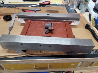
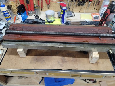
The inside of the saddle had some rust or lacking paint coverage so I cleaned that up and gave it a bit of primer as I don't plan to pull that out anytime soon, all the leadscrew nuts were also caked in grease which is bad and took a bit to get fully cleaned.

20210516_074911.jpg

20210516_074923.jpg
machining on these parts looks okay no scraping on the saddle at all

20210516_100716.jpg
the base or y axis has pretty nice looking scraping. I did also pull the y axis leadscrew clean and lightly stone.

20210516_173420.jpg

after putting the saddle and y axis gib back in i adjusted the backlash on the Y axis screw, adjust the gib within reason and then tightened down the bot holding the saddle to the leadscrew nut checking full range of movement.
20210516_173405.jpg

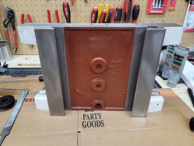
table inverted for cleaning has much better coverage of primer on the interior castings. once again cleaned everything especially the leadscrew of the facotry grease and lightly stoned, the leadscrews are pretty good but occasional burrs so I felt justified.

20210516_173411.jpg

interesting oiler solution for the ways just a ball oiler and a hole and its from the table side vs the saddle. no scraping but kind of looks a bit like it but I think they are just milling marks though may work similar I'm no expert.


20210523_132042.jpg

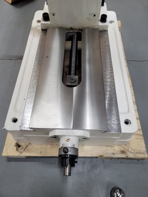
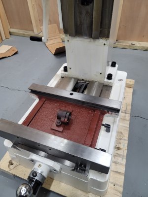
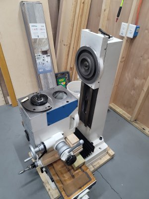
got the table back on and just thoroughly blocked up the head lowered it down onto the table and used the Y axis to pull it back away from the Z "saddle" is that the right term?

20210526_220303.jpg

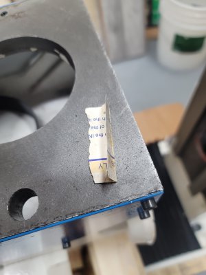
when i separated the head from its "saddle" this nifty piece of paper fell out which it turns out was a shim (later more info when tramming) love the ingenious solutions :)

20210523_132053.jpg
had some surface rust in the pockets on the back of the head to cleaned them out oiled and then stoned the rotating face

20210526_125642.jpg

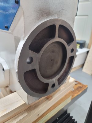
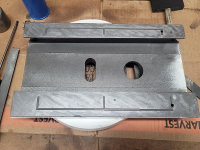
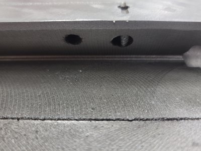
removed the z axis saddle, stoned the rotating face, flipped over to find a coarser but pretty decent scraping oil grooves sweet but no way to feed them???? more on that in the next post.
 
Nice, I like the swirl effect on the chip tray.
 
Nice, I like the swirl effect on the chip tray.
thanks, my first stab at that sort of thing came out okay I just knew the chip pan was going to get dinged up over time so may just leave it a bare metal color so swirled it and clear coated it to protect it somewhat.

Anyhow continuing the interesting adventures of cleaning and disassembly, I decided lets punch some holes to access the oil grooves even if its just to put ball oilers in there for the z axis ways and maybe one day I would thank myself if I ever went to a one shot system.

20210601_120836.jpg
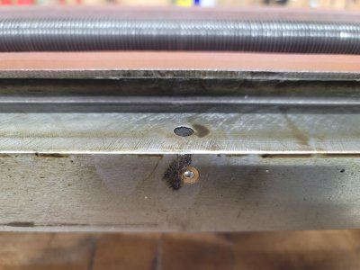
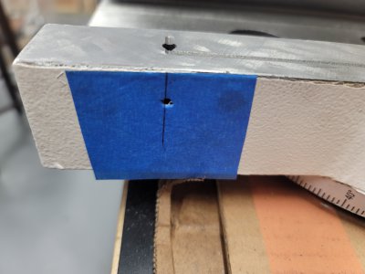
taped and marked where it should line up center punched in and the punch shapely went in, was like wth is going on here

20210602_073852.jpg

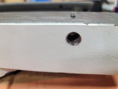
turns out just body filler packed in a M11 threaded hole, a classic case of hrmm this feature cost to much to put a oiler or anything in just bondo it over. still glad it was there curious if the other 932's have it.

20210601_120850.jpg

can see from the inside there was a hole and to be fair i was wondering how they would have bored it from the inside and ofc it all makes sense after the fact. for now i just got some grub screws with Teflon tape on them to seal the holes till i get a decent solution to adapt them to oil fittings.


cleaned the leadscrew for z and also lightly stoned it i didn't full remove it as it seemed quite annoying to do so so this was done in situ

20210516_075023.jpg

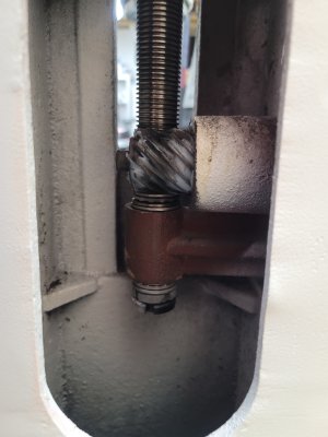
one of the two spots that use grease think that is still the factory i cleaned it mostly off. not terribly dirty in the column but some here residules of the sand casting paint overspray etc. Other thing of note the top cap that holds the top end of the leadscrew doesnt have any bushing material leadscrew rubs right on the cast iron cap piece, not sure if a issue or not but a interesting observation. No keyways or anything on the top end of the leadscrew so it doesn't seem super easy to adapt to the Z axis feed like on a 932M variant. as you would need to pull and modify the leadscrew to interface it to something.

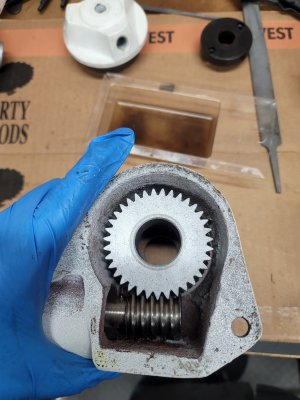
Also did a bit of work on the head after mounting cleaned any of the factory oil off I didnt go into the spindle but i cleaned and stoned the tooth rack on the outside of the spindle and took apart and cleaned the manual downfeed really simple system but thought it worth it to show a pic as well i only seen pics of the PDF setup

20210516_082149.jpg

also worth noting that the ends of the worm gear are razor sharp spent some time dressing them up and stoning that ( also spot 2 that uses grease)

that covers pretty much most of my takedown and disassembly experience its really not too bad lots of simple machines at work together in a somewhat precise way. quality seems about as expected for a china made tool can definitely see the differences in fit and finish compared to say the older Taiwanese grizzly lathe i am currently working on cleaning/rebuilding though that being said you can see where both cut corners.

I would definitely still recommend a cleaning lots of the factory oil/cosmoline and some dirt/**** to clean out but honestly not to bad in terms of dirt and or other contaminates at least on my unit. that and it helps to give a better understanding on how all the bits work together (at least to a new person to machining such as myself.)
 
Next I figured I would share a few pics of the stand, my Dad was kind enough to help with most of the welding& construction as I don't have a welder. I did love scouring the internet for ideas so figured i could share some pics of it, I can also probably get a copy of the actual design and post that up if needed my dad drew it up in solid works (works as a design engineer by trade)

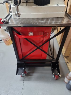
Being about 6'2" the stand you can get from PM is monumentally short and given that my shop is small i wanted to try packing some storage under it, found the "shortest heaviest and cheapest" tool chest to build the stand around think its a craftsman 2000 series if memory serves me right. not the best but not the worst. work height all said and done is pretty much perfect for me no hunching over.

20211108_125831.jpg
side view you can see the cabinet is shorter that the mill is deep

20211108_125847.jpg

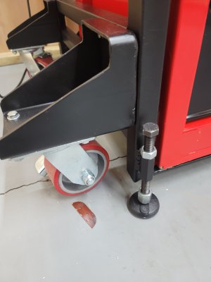
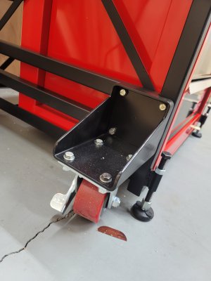
close up of leveling feet and castors feet are rated at 1500 lbs ea. so plenty locking nut to hold the position

20211108_125852.jpg
wheels are designed as removeable if they ever get in the way.

20211108_125911.jpg

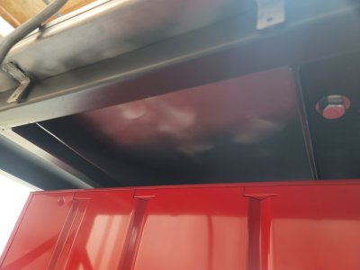
not super stellar but as a afterthought a pic from underneath tube stock and inverted angle irons support the sides of the machine front and back rest over the frame. tabs added to the sheet so it could be tacked down if it vibrates too much. bolts go up through the bottom in the event that they come loose or free I can at least see that it happened from the top side.

Next up tramming and first chips (last one almost there wooo)
 
So here we are finally tramming and getting ready to make some chips.

20211107_090100.jpg


Figured I would post tramming numbers some as i know less of how good or poor they may be to comment I haven't converted the manuals MM measurements to in but plan to do so yet too. using dial indicator and test indicator from shars marked by .0005 for reference.

X Gib check, table extended measured a max play of 0.0015 and easy enough to move think im happy with that

Y gib check, couldn't figure how to measure but think its decent at least brought it up to snug to move and backed it back just till it moved pretty easy.

Z gib check, oof cant do by feel as the crank is awful tried to indicate it and push on the motor or head some but probably could use a better look


Z-Axis
Over a distance of ~4" using a square I trust to be square for sake of sanity
relative to X: 0.0015" (this is the worst measurement on the whole thing)
relative to Y: 0.0005

Spindle Squareness: taken from a "normal operating height of the head"
over a distance of ~5" using a square I trust to be square for sake of sanity
relative to X: 0.0005"
relative to Y: 0.0005"

*Notes* discovered the joys of tramming the tilt of the head and as you tighten the bolts it can move a fraction on you :) as to the Y or the nod it turns out that paper was critical I added .001 of brass shims to bring the nod into shape (trial and error after about 5 combinations)

Table "flatness": (bad term but what I jotted down in my notes)

so here less sure how to measure everything but enjoy the following grid attempt at depiction
8in to the leftcenter of bed8 in to the right
second island between tslots00.00050
first island between tslots.00050 (origin).0005
front edge-0.001-0.0005-0.001

swept a 8 in circle around the center of the table max variance was .0005

*notes* I'm not exactly sure how to interpret said pattern, i know the table when put all to one side wants to lift a little as there is say 5lbs or so hanging off one end lifting it. the y axis variances don't entirely make sense overall for now I'm in the camp of live with it the max we see across it is a total of a thou which for a import china mill doesnt "seem" bad but what do I know

T-slot parallelism: think this is close to the right term

8in to the leftcenter of bed8 in to the right
top edge closest to column0.000250 (origin for slot)0
top edge middle0.000750 (origin for slot-0.0005
top edge closest to front0.000250 (origin for slot)-0.0005

*notes* i know here i went down to .00025 my graduations are only .0005 but these measurements were so consistent i feel confident enough when the needle sits firmly between the two tics to call it .00025

don't have a good way to test spindle runout


tramming in the vise or squaring it up was a fun experience to say the least watching things move as you tighten down the nuts :) I should have checked square or flatness but honestly i just trusted it was flat and I wanted to make some chips.

20211107_115844.jpg


So I should add or admit I did ruin a endmill thinking i was understanding feeds and speeds, and well it was a cheap PM endmill the second endmill had much nicer ground cutting surfaces too which i think helped 3/8 HSS 2000rpm and fed at 6 IPM I did take a stopwatch to my powerfeed to dial that in till i get a better feel of things. just cutting some scrap aluminum that was super jagged on the edge. used a bit of wd40 as coolant should at least thing about getting a air setup.

but finally after a few months things are all together and operational now I can start to play and learn more.

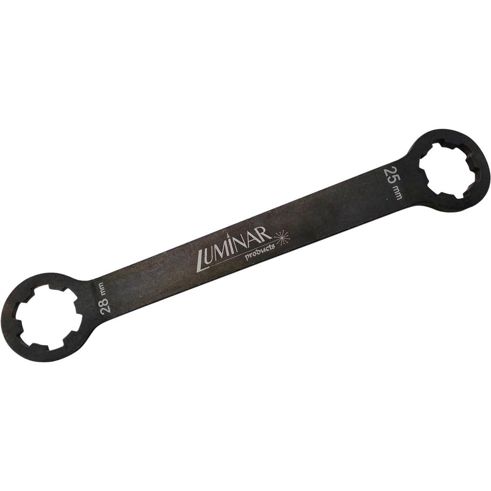
Also as a side note or question how the heck are you supposed to tighten the draw bar without a spline wrench? I imagine the geared head machines you put it in gear? but this is belt drive its spins free as a bird.
 
 
Excellent description of prepping a mill. Thanks.

There may be a pair of flats on the bottom extension of the spindle, a spanner holds this while you tighten (or loosen) the drawbar.
 
Looking sharp! ....loving the Damaskeening on the chip tray! :)
 
Excellent description of prepping a mill. Thanks.

There may be a pair of flats on the bottom extension of the spindle, a spanner holds this while you tighten (or loosen) the drawbar.

I know I missed a lot of pics of various bits but I tried to describe everything its easy to get absorbed in what you are doing.

and as to the spindle its completely round unfortunately, i think the spindle wrench Aukai posted is my best bet as my jerry rigged solution so I could make chips is not a great long term idea. Think though overall not including a spline wrench or flats at the bottom is just poor design seriously how is anyone supposed to be able to use it
 
Back
Top