Treadmill motor conversion for planer feed - running too fast

KevinH

Registered
Registered
Joined
Mar 31, 2020
Messages
22
Hi there,

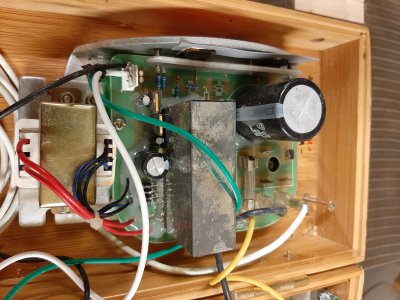
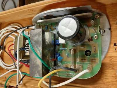
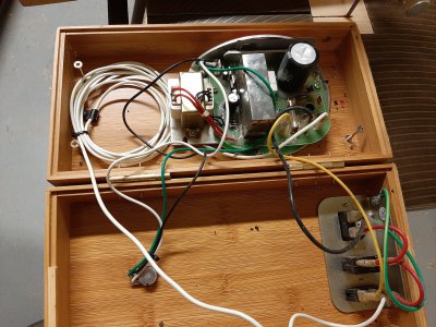
I have a nice old Inca planer thicknesser that I have been slowly fixing up over the years. Originally these come with one motor that runs both the cutterblock and, through a system of gears to slow the RPMs, the feed rollers. On the machine I got the gears were unfortunately all bust up, being one of the only plastic parts of this machine. I decided to bypass the gears and try run a treadmill motor directly to the pulley that drives both feed rollers. I got it installed and wired with the original treadmill circuit board (a PWM if I remember correctly?) and a potentiometer for speed control.

It runs perfectly well except that even at it's very slowest it is far too fast for planer feed rollers. (It would be excellent as a wooden board cannon though, shooting them across the workshop!:guilty:)

Is there any way to slow this motor - using a potentiometer that only works for the lower end of the spectrum (if these exist??) or is my goose cooked on this project? There's not enough space in the cabinet of the machine for a countershaft.

Also, will the motor even have enough torque at this low a speed?

Is it time to fork out on a 3 phase motor and VFD?

Inca don't exist anymore, so parts are hard to find and expensive if you can find them.

Any help would be appreciated!
Thanks,
Kevin
 
You have a couple of options:
1- Have the treadmill motor connect via reduction gearing
2- use your own controller that can do a lower PWM signal.
3- Modify the current circuit board to do a lower speed.

For #3, can you take a picture of the board? Those controllers often have a 'min' and 'max' setting via a POT. If you can snap a picture of the circuit board, someone might be able to spot one.

The fear to using this motor is that it might just not have enough power at lower RPMs to work in the planer. You might find adding some gearing/belt to be your best option for that.

Finally-- Any reason you couldn't just spend the ~$40 for a new Boston gear of the right size and use the factory setups? Or do you like the idea of adjustability?
 
I just reread this:

I decided to bypass the gears and try run a treadmill motor directly to the pulley that drives both feed rollers. I got it installed and wired with the original treadmill circuit board (a PWM if I remember correctly?) and a potentiometer for speed control.

Just get different pulleys! Put a smaller one on the motor, or a bigger one on the roller side (or both!). You'll essentially be just changing gear ratios.
 
Bigger pulleys!
I actually thought of that on day one but couldn't get the big fly wheel pulley off the motor spindle so put it out of my mind.

I'll double check when I'm back in the workshop later, space is tight but it might work.

If there's an electronic fix to complement the bigger pulleys that could be handy. Here's a few photos of the board. It's in a temporary box.

I'm not aware of Boston Gear... What is it exactly? Adjustability would be nice but in reality I think once I dial in the right feed rate I probably won't adjust it much. I'd prefer to have this working without adjustability than not working at all at this stage

Thanks for the help Erich! Appreciate it.
 

Attachments

  • 20200331_202750.jpg
    20200331_202750.jpg
    1.7 MB · Views: 31
  • 20200331_202814.jpg
    20200331_202814.jpg
    3 MB · Views: 39
  • 20200331_202803.jpg
    20200331_202803.jpg
    3.8 MB · Views: 37
Hi Kevin,

Welcome to the Hobby Machinist!

You have already been given some great feedback and ideas by @ErichKeane above.

I can offer one more option......3D-printed replacement plastic gears.
Many metal cutting lathes are using plastic gears in their feed systems.

You would have to know the specification details of the original gears; pitch (or modulus for metric), tooth count, bore size, thickness, pressure-angle, etc.

I could print the gear(s) you need and send them off to you.
No charge, if you promise to post an open and honest review right here of if and how well they work for you.
It would honestly cost me less than two dollars in material.

Alternately, if you have a place to print them yourself I could provide the .stl file that the printer needs as input (given all the specs above).

Any idea what material the original gears were?
I usually print in PLA plastic since it is so easy. Nylon would also be an option.
I have printed a little ABS, but I need to move the printer out to the shop for that because of the smell.

I will try to post back with some pictures of 3D-printer gears.

-brino
 
Thanks Brino!

That's a very generous offer. However I don't think it's the road I'd go down here. I'll take a photo of the original gears so show you, they're not just standard sprocket type gears. Also they are grouped together in a 'planetary' arrangement inside a bigger metal cog and some of the spindles on that are missing or worn down.

It could be done but it's a pretty big job and I just don't have the time to rebuild it.

I appreciate the offer though!
 
Bigger pulleys!
I actually thought of that on day one but couldn't get the big fly wheel pulley off the motor spindle so put it out of my mind.

I'll double check when I'm back in the workshop later, space is tight but it might work.

If there's an electronic fix to complement the bigger pulleys that could be handy. Here's a few photos of the board. It's in a temporary box.

I'm not aware of Boston Gear... What is it exactly? Adjustability would be nice but in reality I think once I dial in the right feed rate I probably won't adjust it much. I'd prefer to have this working without adjustability than not working at all at this stage

Thanks for the help Erich! Appreciate it.
Check out that 'speed' and 'amp' Pot (blue, adjusted by a screwdriver!) in the 2nd photo. Those are likely some mild adjustments that will change the motor speeds.

A bigger pulley on one side, or a smaller one on the motor, or BOTH can help!

"Boston Gear" is a company that makes a ton of kinds of gears, but Brino's idea of 3d printing them (and you saying they are oddballs) is likely the best bet for replacement gears.
 
another route maybe an AC gearmotor high torque unit--under 10 rpm. there are some on eba for $30-$50
 
another route maybe an AC gearmotor high torque unit--under 10 rpm. there are some on eba for $30-$50
Thanks for the suggestion Dave. I had a look on eBay and they seem to be fairly small units. It does say high torque but they still look on the small side to me. It will have to push 2" thick hardwoods up to 10" wide into a cutterhead against it's will and I'm not sure they could handle it. I might be wrong though!
 
Check out that 'speed' and 'amp' Pot (blue, adjusted by a screwdriver!) in the 2nd photo. Those are likely some mild adjustments that will change the motor speeds.

A bigger pulley on one side, or a smaller one on the motor, or BOTH can help!

"Boston Gear" is a company that makes a ton of kinds of gears, but Brino's idea of 3d printing them (and you saying they are oddballs) is likely the best bet for replacement gears.
I will definitely try adjusting those Pots!
 
Back
Top