- Joined
- Feb 8, 2014
- Messages
- 11,144
.... or why spend $8K on a machine when you can build one for $25K. In the true Hobby Machinist tradition, why buy one when you can build it, and spend more doing it? 
As part of our Stable Camper product, we have to cut and polish 1.5'' aluminum tubes ranging in length from about 30'' to 80''. After we work our machining and assembly magic on them, they need to be polished before they go to powder coat. We normally make runs of about 500 tubes at a time, and hand polishing them in the lathe with Scotch Brite pads is a PITA and normally takes about 2.5 to 3 days for a run. Way too much time, effort, and a mess of fine aluminum powder all over everything. We looked at farming this out, but couldn't get lead times that were within reason.
So the obvious solution is to acquire a tube polisher, many designs are available but the most reasonable solution for our needs seems to be the rotating sanding belt type.
But this is about a $8K machine, if the prices have not gone up since we last checked a year or so ago.
We can build this for about $3K in materials, and a lot of design time and chip making labor. So as of right now I have about 2 weeks of design and drafting time in @ $120/hr, or about $9600 so far and I'm not close to finished yet. I've also purchased about $800 in parts so far. The good news is that when I'm working for myself, I can pay me in cheese burgers. I figure about 2 weeks of chip making and fabrication once I get the designs completed. Since I finally learned (and am still learning) 3D modeling I find it saves me a lot of shop time and I make fewer design mistakes. I can catch the mistakes on ''paper'' before I turn perfectly good material into scrap. It's really easy to make changes with a few mouse clicks.
The main wheel will turn at about 300 RPM and with the 18:1 drive on the pinions, the belts will run at about 5000 FPM, right in the optimum range for aluminum polishing. I ordered a 2HP single phase motor to run it, but I may have to go with a 3 phase motor and a VFD to get variable speed. We'll just have to try it and see how it works out at a single speed. The commercial machines seem to have a variable speed on both the wheel and belts using some sort of coaxial drive system and 2 motors, I hope my single motor design does not come back to bite me.
The one thing that the commercially available polishers seem to be missing is a dust collection system. Mine will have a downflow suction system connected to a Harbor Freight 2HP dust collector. https://www.harborfreight.com/2-hp-industrial-5-micron-dust-collector-97869.html The sheetmetal guards will be designed to direct the air flow where it's needed to remove the dust, and hopefully keep most of it out of the works.
That aluminum dust is nasty as well as being explosive. Also, this machine will be forklift portable and will only be used outside, never in my shop.
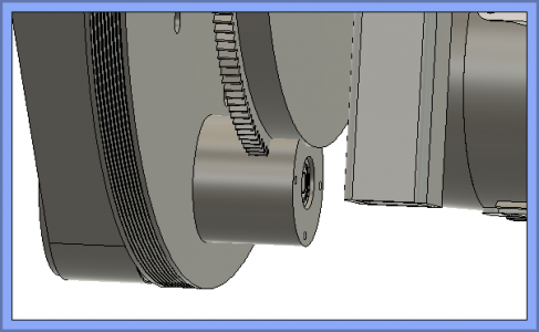
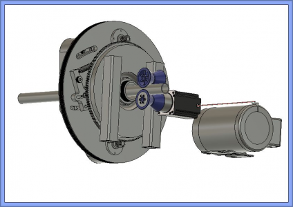
On with the show.... The unfinished assembly drawings. Uses standard 2 x 42 sanding belts. I'm trying to use as many off-the-shelf parts as I can, saves a lot of time. The main wheel will be 20'' diameter x 1'' thick aluminum. The Poly-V belt grooves will be machined into the OD, using the ''J'' profile.
Front side
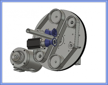
The back side
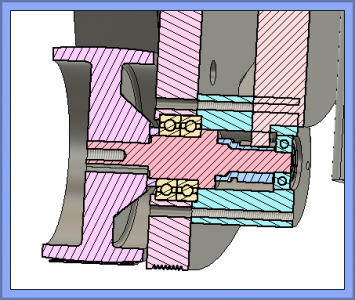
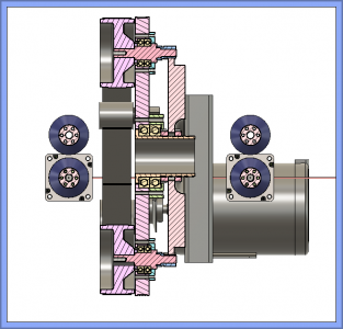
And a detail cutaway.
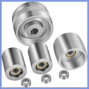
The belt wheel kit is from Amazon https://www.amazon.com/VEVOR-Comple...elt+sander+wheels+2x48&qid=1651692894&sr=8-12
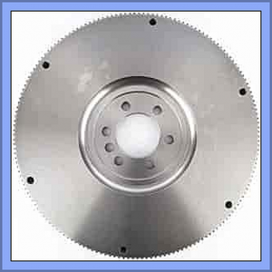
The flywheel is small block chevy, it serves as the main support for the works as well as providing the drive for the sanding belts. The pinion gears are standard chevy starter gears.
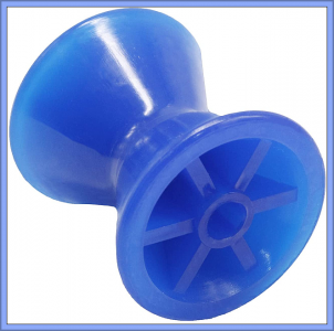
The feed rollers are 3'' boat trailer bow bumpers, and will be somewhat modified to fit. https://www.amazon.com/dp/B0913BCWTS?psc=1&ref=ppx_yo2ov_dt_b_product_details
I have one of these and they seem pretty substantial.
More later.......

As part of our Stable Camper product, we have to cut and polish 1.5'' aluminum tubes ranging in length from about 30'' to 80''. After we work our machining and assembly magic on them, they need to be polished before they go to powder coat. We normally make runs of about 500 tubes at a time, and hand polishing them in the lathe with Scotch Brite pads is a PITA and normally takes about 2.5 to 3 days for a run. Way too much time, effort, and a mess of fine aluminum powder all over everything. We looked at farming this out, but couldn't get lead times that were within reason.
So the obvious solution is to acquire a tube polisher, many designs are available but the most reasonable solution for our needs seems to be the rotating sanding belt type.
But this is about a $8K machine, if the prices have not gone up since we last checked a year or so ago.
We can build this for about $3K in materials, and a lot of design time and chip making labor. So as of right now I have about 2 weeks of design and drafting time in @ $120/hr, or about $9600 so far and I'm not close to finished yet. I've also purchased about $800 in parts so far. The good news is that when I'm working for myself, I can pay me in cheese burgers.
 I figure about 2 weeks of chip making and fabrication once I get the designs completed. Since I finally learned (and am still learning) 3D modeling I find it saves me a lot of shop time and I make fewer design mistakes. I can catch the mistakes on ''paper'' before I turn perfectly good material into scrap. It's really easy to make changes with a few mouse clicks.
The main wheel will turn at about 300 RPM and with the 18:1 drive on the pinions, the belts will run at about 5000 FPM, right in the optimum range for aluminum polishing. I ordered a 2HP single phase motor to run it, but I may have to go with a 3 phase motor and a VFD to get variable speed. We'll just have to try it and see how it works out at a single speed. The commercial machines seem to have a variable speed on both the wheel and belts using some sort of coaxial drive system and 2 motors, I hope my single motor design does not come back to bite me.

The one thing that the commercially available polishers seem to be missing is a dust collection system. Mine will have a downflow suction system connected to a Harbor Freight 2HP dust collector. https://www.harborfreight.com/2-hp-industrial-5-micron-dust-collector-97869.html The sheetmetal guards will be designed to direct the air flow where it's needed to remove the dust, and hopefully keep most of it out of the works.
That aluminum dust is nasty as well as being explosive. Also, this machine will be forklift portable and will only be used outside, never in my shop.
On with the show.... The unfinished assembly drawings. Uses standard 2 x 42 sanding belts. I'm trying to use as many off-the-shelf parts as I can, saves a lot of time. The main wheel will be 20'' diameter x 1'' thick aluminum. The Poly-V belt grooves will be machined into the OD, using the ''J'' profile.
Front side

The back side

And a detail cutaway.

The belt wheel kit is from Amazon https://www.amazon.com/VEVOR-Comple...elt+sander+wheels+2x48&qid=1651692894&sr=8-12

The flywheel is small block chevy, it serves as the main support for the works as well as providing the drive for the sanding belts. The pinion gears are standard chevy starter gears.
Amazon.com: JEGS Flywheel | For 1971-1980 Small Block Chevy 400 | External Balance | 168 Tooth | Fits 2-Piece Rear Main Seal | Non-SFI | 14.125” Diameter : Automotive
Buy JEGS Flywheel | For 1971-1980 Small Block Chevy 400 | External Balance | 168 Tooth | Fits 2-Piece Rear Main Seal | Non-SFI | 14.125” Diameter: Transmissions & Parts - Amazon.com ✓ FREE DELIVERY possible on eligible purchases
www.amazon.com

The feed rollers are 3'' boat trailer bow bumpers, and will be somewhat modified to fit. https://www.amazon.com/dp/B0913BCWTS?psc=1&ref=ppx_yo2ov_dt_b_product_details
I have one of these and they seem pretty substantial.

More later.......


 We used to clean up our conveyor rollers on the big lathes . We made up a belt sander which mounted on the tool post and engaged the feed . Saved countless hours . Always found your projects enjoyable Jim . Keep us posted on the progress .