Tube Polisher....

I'm late to the party, but I wonder why you didn't use a centerless grinder as a basic design? It would seem you are doing something similar, and those are often designed for work to flow through continuously.
I looked at that type when I was researching methods and it was my #2 choice. It really looked more complicated and higher maintenance than the rotating belt type. Also it is a less compact design, and space is at a premium in our shop. I thought about a hybrid design that used a sanding belt rather than a flap wheel or ScotchBrite wheel. But the biggest drawback is the need to rotate the workpiece as it feeds through the machine, I really wanted to avoid that due to the complexity of angled drive wheels.
Its bad form to retain two regular deep groove ball bearings like this. If both inner and out races are trapped you run the risk(pretty high) of forming a preload and damaging the bearings prematurely. They make double row ball bearings or you could use angular contacts but both are pretty expensive and unnecessary for an application such as this
Yes, you are 100% correct. What you don't see in the drawing are the shims and axial running clearance in the bearing assembly. I just didn't draw them, this is stuff I do during machining and on assembly. If these were ''real'' shop drawings that were going out to a shop for fabrication, the clearance would be shown on the drawing. For in-house use, I don't need those notations.
 
Got a little more work done, this is going slowly because I'm old and slow :)

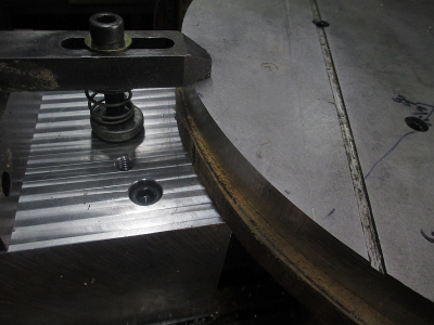
Got the clamp system completed. It was a bit tricky to drill through 5.6'' of aluminum with a 6'' long drill bit for the mounting bolts. I had to flip it over and finish drill from the back side. Came out good, can't even see where the holes met, sometimes you get lucky. Just clearance holes anyway and I was using a 17/32'' bit for standard clearance for a 1/2'' bolt. Precision was not really required. About 30 lbs of aluminum there.

1655837420406.png

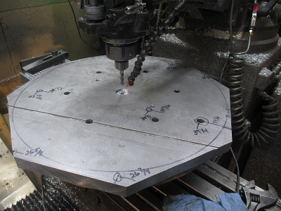
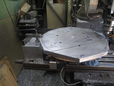
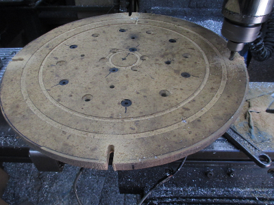
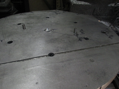
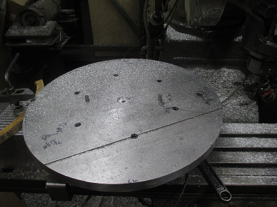
Got the aluminum plate mounted up on the RT and machined the center locating pocket and drilled & reamed the dowel pin holes so now I can reset 0 if needed.

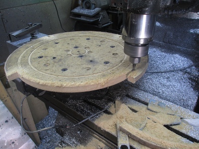
Today I'll get the OD roughed out. That is going to be a long process, I have to do it in about 15° increments because I can't use the RT to drive the process, my 6'' RT is just not big enough to handle those kind of machining loads on a 20'' circle. So clamp, machine, unclamp, rotate, rinse/repeat. Also I can only move Y+ about 2.75'' max due to clearance issues, so this drastically reduces my work envelope.

I really need a bigger machine to make this part, but you make do with what you have. It just takes some creative setup to make it happen, there is always a way. It will take a couple of days to do all the machining on this part on this machine. On a bigger machine, maybe a 60x30, it could be all done in about 45 minutes because you could work all the way around the part, and would not need a RT.

1655837751961.png


More Later.....
 
Last edited:
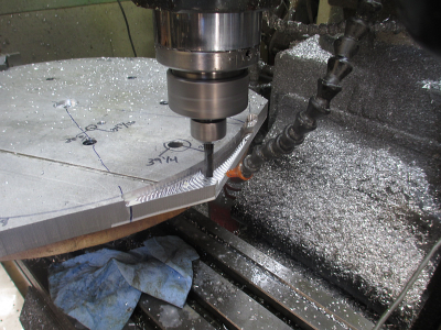
I got started on roughing out the circle, and then stopped. This was going to take forever, 160 minutes for about 90° of material removed as shown below.

0.270'' step down/pass, 0.180'' engagement, 8 IPM, 4 passes per rotation. I did find out I can rotate 45° per cut rather than the 15° I thought I was going to have to use.

Going to create a new tool path using a full depth cut (1.00'') with only 0.050'' engagement and speed up the feed rate to 20 IPM. According to my calculations it should be about 22 minutes per rotation. We'll see if my machine and setup can handle that. According to the end mill manufacturer's specs, even at that I am still babying the tool. But my machine is not a 10K RPM VMC with flood coolant.

1655868144816.png

1655867993897.png

We'll see how this works out tomorrow. :cautious:
 
Nice work, especially the work arounds given the limitations. If we all had equipment that didn't require it, we would have no time to do our own projects.
 
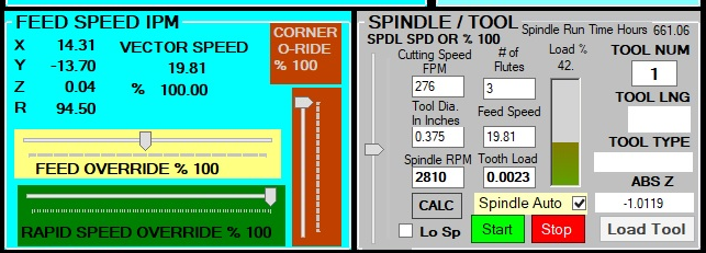
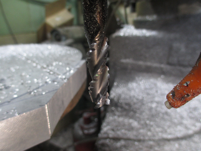
I created the new tool path and tried it out this morning. It went well. I have a new found respect for modern cutting tools and tool paths. Cutting time went from 80 minutes to 26 minutes.

A screen shot of the cutting parameters while it was running. 1'' deep, 0.050'' stepover per pass

1655944225220.png


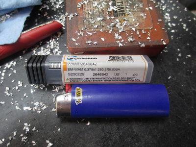
This is the tool I was using for this roughing operation. LMT-Onsrud, 3 flute, 3/8'' dia. Back in the old days you would snap a carbide tool trying make this cut. Carbide tooling has come a long way in the last couple decades or so, as tough as HSS and lasts 10 times as long. We run these at 6K RPM and 80 IPM in the Haas with a 1'' depth of cut. My old Eagle won't quite do that. Modern cutting strategies make a huge difference also.


1655944631698.png

1655944454526.png

But then..... A problem...... My rotary table stuck. o_O $&*@#$.

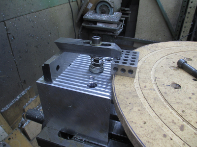
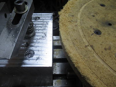
It turned out that the MDF spoil board that is under the aluminum plate swelled a bit with the coolant. The MDF is also part of the clamp system that I built. The top of the clamp block is the same height as the RT top, so when the MDF swelled there was a tight interference with the top of the clamp block, enough to stop the RT from turning.

1655945990253.png

So remove the work and do a bit of surgery on the MDF. First cut some notches to handle the cut off pieces.
1655946129378.png

Then cut off about 3'' off of the OD

1655946278099.png

Now no interference. The MDF does not need to be at the edge of the work anyway

1655946362596.png

This is why we use dowel pins, allows removal and replacement of the part without having to set everything up again. These go down into the cast iron adapter plate, under the MDF. And since I reamed the holes at 0.376, I can pull them out with pliers.
1655946676356.png

The clamp now requires a spacer to work. I just used a piece of the cutoff MDF that had not been affected the coolant yet.

1655946964925.png

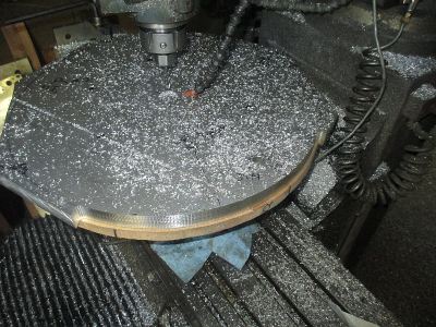
Back In business and the circle is roughed out. Next, the finishing cut. That will be a 0.010 stepover helical down cut using the RT to feed. I'll generate the tool path tonight.

1655947700245.png
 
Last edited:
Got the finish cut on the OD completed today. I had to use the RT as the feed, and 0.010'' stepover was about all the RT would take at a 35 IPM feed speed. It's a little tricky to calculate the feed speed on the OD of a circle and try to relate that to IPM. Fortunately I have a Shimpo handheld tach and it is scalable in many different units, including IPM using the linear speed wheel. So just played with the feed until I and the machine were happy.

I hand wrote a program to make the finish cut because I am not about to pay Fusion for their 4th axis (used to be included at no extra charge) addin that I might use once a year. It was a simple program, about 10 lines of G code. Create a helix toolpath by moving Z down in relation to the rotation.

G1 Z-1.020 A-2160.0 F10. (While Z feeds down from 0.05 to -1.020'', rotate the RT -2160 deg (6 full rotations), feed 10 IPM)
This gives about 0.250 step down per rotation in a nice smooth helix. I had to make 4 passes because I left 0.040 for cleanup from the roughing cut. Came out great. :)

1656050305685.png

For the next operation it's even more fun, the poly-V pulley grooves in the just finished OD. These grooves are J profile, so about 0.093 deep.
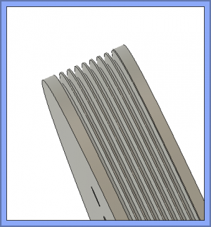
1656051509950.png

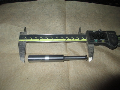
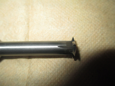
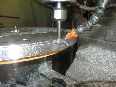
Required a special cutter because the V's are 40° I was able to locate one at Harvey Tool. https://www.harveytool.com/products/tool-details-967510

Spindly looking tool I hope it survives. :cautious:
1656052689487.png

1656052739152.png

Again I had to hand write the G code for this operation, but this is a simple one also.

The code below is written to do only one pass per groove. I may chicken out and do them in two passes. :eek:

G0 X10.157 Y-1.850 Z0.6 (Set X, Y, & Z to the start position)
G0 Z-0.212 (Move Z down to the first groove height)
G1 Y0.0 A90.0 F10. (Lead into the work)
G1 A450.0 F10. (Rotate one revolution)
G1 Y1.850 A540.0 F10. (Lead out of the work)
G0 Z0.6 (Raise Z 0.6'' above work)
G0 X10.157 Y-1.850 A0.0 (Reset position to start )
Rinse/repeat for all 8 grooves.
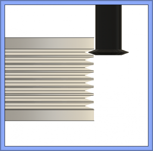
1656052596477.png

All of this would be easy if I had a 20''+ swing lathe. But we use what we have and just figure out how to make it work. Machining is just solving a series of problems to achieve a desired outcome.
 
Last edited:
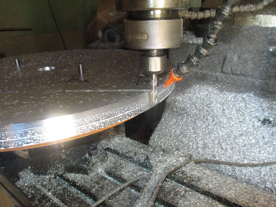
OK, that did not go well. :eek: I chickened out and decided to make 2 passes rather than one pass / groove. Well, that proved to not be enough either. Because of the taper angle of the cutter, I decided to take 60% depth on the first pass and the remaining 40% on the second. With that taper angle, the volume of material removed per pass increases something like the square of the cut depth (I didn't do the math to exactly calculate it), so decreasing the depth of the cut per pass is the correct approach.

The first pass went fine but the second was removing too much material for the tool and I got the dreaded BUE (Built Up Edge), aluminum welded to the cutter. The good news is that I was able to get it shut down without damage to the tool or part.

First pass. I'm always amazed at the shutter speed of my cheap point & shoot Cannon camera. That spindle is turning about 2600 RPM in this picture, no motion blur at all.
1656173491541.png

So I rewrote the G code last night and will now make 8 passes at decreasing stepovers, finishing with only 0.002'' engagement on the final pass. At 7 minutes/pass this is going to take awhile, roughly 8 hours to complete the 8 grooves. I can get the yard mowed and get a nap in while it's running, I don't need to stand there and watch it.

We'll see how this goes today. :cautious:
 
Jim,
I really appreciate you sharing this design and build. I enjoy doing design/build projects myself, although mine are at a much simpler. Seeing your projects encourages me to press onward. Please continue updating us on your progress. Thanks!
 
Jim,
I really appreciate you sharing this design and build. I enjoy doing design/build projects myself, although mine are at a much simpler. Seeing your projects encourages me to press onward. Please continue updating us on your progress. Thanks!
Thank you for the kind words.

My goal is to educate and show how I solve the problems associated with machining projects. This of course is not the only way to do something, but rather how I approached the job. Hopefully someone else can find an idea that will be useful to them in their project.
 
Back
Top