Understand unloader valves

Thanks, I thought so. bet this is a copy of top end VFDs and has the same functionality. the Chinese are good at copy :)

Just need to brush up on my chinglish, bet the manual on this thing is poor. I got till June 5 - long delivery time.
 
Assuming you are using an HY VFD, you might look at PD050-51 (Multi-output 1 (DRV/UPF)), if programmed to 05 = Set Frequency Reach on the HY model. This would trigger DRV output rated at 24V/100 mA so this could trigger a relay to control a solenoid. Also there is PD052-53 which operates the relay for FA, FB and FC; KA and KB. They do not give a description, but it should operate with the same parameters as PD050 "Multi-Output", so setting it to 05 = Set Frequency Reach should also work. The relay is rated at 3A/250VAC/30VDC so should be able to directly operate a solenoid. Other option is a delay triggered solenoid set at something like 3-5 seconds.

If your compressor has an oil pressure gauge, then it uses a pressurized lube system.
 
Last edited:
Assuming you are using an HY VFD, you might look at PD050-51 (Multi-output 1 (DRV/UPF)), if programmed to 05 = Set Frequency Reach on the HY model. This would trigger DRV output rated at 24V/100 mA so this could trigger a relay to control a solenoid. Also there is PD052-53 which operates the relay for FA, FB and FC; KA and KB. They do not give a description, but it should operate with the same parameters as PD050 "Multi-Output", so setting it to 05 = Set Frequency Reach should also work. The relay is rated at 3A/250VAC/30VDC so should be able to directly operate a solenoid. Other option is a delay triggered solenoid set at something like 3-5 seconds.

If your compressor has an oil pressure gauge, then it uses a pressurized lube system.
I bought a nice ten horse quincy air compressor at auction. Worked there, not when I got home :(

First was electrical. installed new contactor and relaced burnt up wiring. Still no joy.

Went completely through head. Removed ten pounds of burnt carbon several reed valves and springs. Man was it a dirty mess. Still does not run, but I am close.

The unloader valve is not releasing. If I undo the unloader valve air line at the blue arrow in the top of quincy pic, the compressor begins pumping.


Look at the unloader valve assembly - side of quincy pic.

I think this stuff is for both an engine type compressor and an electric motor start unit.


View attachment 293837View attachment 293838View attachment 293839

Now look at my tractor PTO unit. This compressor only unloads on high pressure allwoing the PTO to keep turning. Sure looks exactly like the parts in green arrows on the quincy.


Back to the side of the quincy. I want to verify this, but I am pretty sure I've seen compressors with only the bottom device (red arrow in side of Quincy view). So, am I right? all the stuff in the green arrows has nothing to do with starting unloader operation? So, it can be removed? FWIW, the valve ,orange arrow, is turned off.

That still won't get it working. My guess is replace the bottom, red arrow, unit. plumb it direct to the unloader valves on top the compressor.

I may be all wet here, sure would like to find someone that know how it is supposed to work.
Make sure your motoris turning in the right direction. The oil pump will only work if it is turning in the right direction. What is the pressure on the guage when it is running.
 
Thanks for the detail on the outputs, thought HY VFDs had this. This is going to be the PERFECT way to control the unloader valves.

Yep, this unit has an oil pump. I checked it with the hydraulic unloader removed => oil slick across the room.
 
OK, been a while. I ordered a Huanyang VFD on a slow boat from china. My ship finally came in this week.

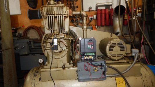
Pic shows everything mounted and wired except the unloader solenoid valve.

This is the programming:
1. Remote
a) wiring: S1 and comm through pressure switch and on/off switch in series
b) parameters
P0.01 to 1 Remote terminal
P5.01 left at default 1 forward run

2. Speed control parameters
P0.03 max freq 60
P0.04 U F L 60
P0.05 L F L 60
P0.06 ref. freq. 60

3. accel and decel parameters
P0.11 AC time 5
P0.12 DC time 5
P1.06 stop mode 1 (coast to stop)

Machine run fine!!!!!! Big day for me. been working on this a LONG time with a mechanical rebuild, then a failed unloader rebuild, then an electrical unloader test, then the VFD install.


OK, ONE JOB LEFT. Would like advice before proceeding.

Need to energize the 110 VAC air solenoid to the unloaders ONLY during machine acceleration.
I copied the four pages about this from the manual. See .pdf

Got a relay output: R01B (NO) and R01C. (NC) can put 110 VAC to R01A common
Can program this P6.02 to 6 frequency reached. manual references P8.23, leave at defalt of 0.0

Have an extra contact on the pressure switch.

I am thinking run 110 power to pressure switch then to R01A. Then connect R01C to hot side of air solenoid.

If pressure switch closes => 110 goes to air solenoid. When frequency is reached R01C opens.


<EDIT> Maybe there are TWO outputs. manual is confusing here. Looks like terminal strip has a second set of outs and manual reference P6.03 for output 2. If so, I'd use this instead of pressure switch.


Quincy running with VFD.jpg
 

Attachments

  • scan.pdf
    1.1 MB · Views: 3
  • scan0001.pdf
    1.8 MB · Views: 2
  • scan0002.pdf
    1,006.3 KB · Views: 2
Last edited:
I am thinking run 110 power to pressure switch then to R01A. Then connect R01C to hot side of air solenoid.

If pressure switch closes => 110 goes to air solenoid. When frequency is reached R01C opens.

If I understand correctly that should keep it unloaded until the motor is up to speed. I have found on mine that just having a 10 second accel ramp works fine, but I only have a 5HP compressor. The starting load never goes over the maximum running load.
 
Thanks Jim. You know I lack confidence on wiring on something new.

Creeping elegance. Don't like VFD powered 24x7 so I'm installing a contactor. Pressure switch close contactor. Jumper S1 to comm. 110 to R01A. R01C to air solenoid.

PARTS OF THIS MANUAL MAKE NO SENSE.

I'd like to display current all the time. somebody tell me how. Manual attached.
 

Attachments

  • scan0003.pdf
    1.9 MB · Views: 3
Creeping elegance. Don't like VFD powered 24x7 so I'm installing a contactor. Pressure switch close contactor. Jumper S1 to comm. 110 to R01A. R01C to air solenoid.

A contactor is not the best way to start the system, while it works, it is my opinion it will shorten the life of your VFD. I would leave the VFD powered up while in the shop, and connect all of the controls to the control side of the VFD. Turn off the breaker to the air compressor when you leave the shop if you like. I leave my VFDs powered up all the time.

I have 2 pressure switches on my system, one for normal operation the other as a high pressure limit. (in addition to the normal tank popoff valves for over pressure)

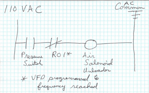
I'm a little confused by your wiring description, maybe a quick diagram would be helpful, a picture of a pencil drawing would do

As near as I can tell, you need to set 7.06, bit 4 =1 to display current.
 
Well, I'll for sure leave it as is if you think its best to leave the VFD on. Don't need more work for no gain.

I ain't no EE, my attempt at ladder logic below.

The current value of P07.06 is 07FF and it displays frequency of drive. its got to be a hexadecimal number. maybe I should try 1000 base 2 in hex??? Or 8??? I do not see how the current default value relates. The manual sort of implies hex, but maybe I'm over thinking it. I will try 8 in the morning and report back.Capture.PNG
 

Attachments

  • scan0004.pdf
    788.2 KB · Views: 3
We're missing something here. How are you telling the VFD to run the motor? The pressure switch should be connected between S1 and COM I think. The output relay should only switch the valve.
 
Back
Top