
McMaster has it at about $30, but its honestly probably a different thing. Regardless another forum member send me a PM and actually had a bearing that wasn't in use, as well as a cross slide that had the round dovetail damaged, and offered to ship them to me.... FOR FREE, so I just want to say thank you to them, and I'll post some pictures as I get the parts installed.

-
Welcome back Guest! Did you know you can mentor other members here at H-M? If not, please check out our Relaunch of Hobby Machinist Mentoring Program!
You are using an out of date browser. It may not display this or other websites correctly.
You should upgrade or use an alternative browser.
You should upgrade or use an alternative browser.
Upgrading Thrust bearing
- Thread starter timpet98
- Start date
Well he said the damage was to the round dovetail thing, I don't know the proper name of it, and as you can see from the picture that I posted of both of mine side by side, that part will be machined off either way. Either way we will see, and I'll let everyone know as my progress continues.
- Joined
- Dec 25, 2011
- Messages
- 10,511
If the damaged part is the inverted cone on the later cross slide, I have always called it the Pintel or pintel. I actually don't know what Atlas called it. I have never seen an Atlas document that referred to it. The closest they come is in the MOLO where it says to keep the square head set screws tight. But if you are going to machine it off, what is going to hold the compound swivel to the cross slide?
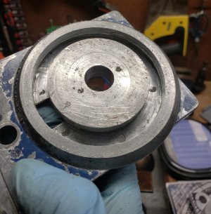
Ya, that is the part that I am talking about. The original 1936 compound rest and cross slide is much like many other larger lathes with a circular t-slot and some t-bolts with nuts on top of the compound rest. As the pic bellow shows the damage to the soft zinc track had begun before I finally did it in and got it locked at 29 degrees. The compound rest has a 5/8 locating pin in the bottem that it rotates about. I'm fairly sure that with some time, careful setup and lots of tiny custom ground grooving tools I could make round t track with the cross slide in a 4jaw. Honestly if they had made it out of cast iron I believe it would be a much more ridgid setup. The other slightly more long term/kinda kills me on the inside slowly, problem with the zinc cross slide is that any grit or chips that manage to find there way under the dove trail get embedded and it basically becomes a lap slowly abrading away the top of my saddle with every part I make. It has carved this one odd groove, I'll send a pic of that when I get a chance.
Attachments
- Joined
- Dec 25, 2011
- Messages
- 10,511
OK.
One thing that hasn't been mentioned are the spindle bearing shims. Under both sides of the bearing cap when it left the factory should have been a 0.010" (originally) shim. Each shim is made of five 0.002" shims glued together. To evaluate the two bearing/spindle conditions requires a dial indication good for at least +/- 0.001" that can be attached to the bed or headstock and measure/indicate spindle vertical and horizontal movement near the bearing caps. First confirm that the four bearing cap screws are properly tightened. Atlas apparently never specified a torque figure but something in the range of 25 to 35 lb-ft seems appropriate. move the end of the spindle that is being indicted vertically and horizontally. Presuming that no chuck is on the spindle, insert something like a piece of 3/4" diameter round bar at least a foot long into the spindle bore. Pull up and push down on the end of the bar to determine the vertical clearance. Push and pull in the horizontal plane to determine the horizontal clearance. Do this at both ends of the spindle. If the vertical movement is greater than about 0.0015", remove one shim wafer from either whichever shim is the thickest or from the front shim if they are both the same. Reinstall the shims and bearing cap and repeat. If still too loose, remove one shim from the thicker shim pack. Continue until the vertical movement with the cap screws fully tightened is under 0.002 at both ends and the spindle still spins freely with little resistance.
One thing that hasn't been mentioned are the spindle bearing shims. Under both sides of the bearing cap when it left the factory should have been a 0.010" (originally) shim. Each shim is made of five 0.002" shims glued together. To evaluate the two bearing/spindle conditions requires a dial indication good for at least +/- 0.001" that can be attached to the bed or headstock and measure/indicate spindle vertical and horizontal movement near the bearing caps. First confirm that the four bearing cap screws are properly tightened. Atlas apparently never specified a torque figure but something in the range of 25 to 35 lb-ft seems appropriate. move the end of the spindle that is being indicted vertically and horizontally. Presuming that no chuck is on the spindle, insert something like a piece of 3/4" diameter round bar at least a foot long into the spindle bore. Pull up and push down on the end of the bar to determine the vertical clearance. Push and pull in the horizontal plane to determine the horizontal clearance. Do this at both ends of the spindle. If the vertical movement is greater than about 0.0015", remove one shim wafer from either whichever shim is the thickest or from the front shim if they are both the same. Reinstall the shims and bearing cap and repeat. If still too loose, remove one shim from the thicker shim pack. Continue until the vertical movement with the cap screws fully tightened is under 0.002 at both ends and the spindle still spins freely with little resistance.
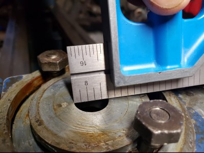
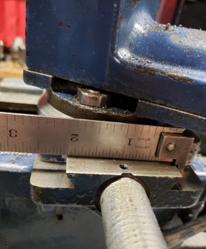
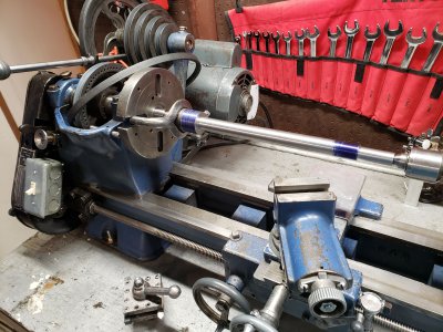
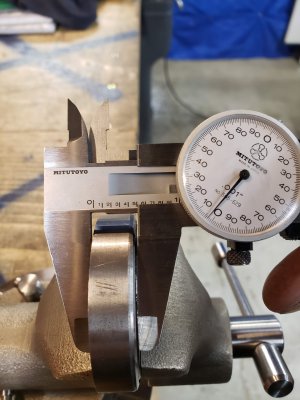
Well I can't remember how thick the shims were when I last had the bearing caps off, but I'll mic them when take it all apart as the bearing comes in. I know that right now I do not have the bearing caps tightened down nearly enough, I don't have a torque wrench so I left them relativity loose. I made the bolts finger tight then added about a 1/16th turn with a wrench. The spindle spins free, but sure it might be too loose. Between the babbitt bearings and the preload of the not really a bearing spacer it got tight real fast with much more tightening. I am fairly sure the chuck more than 2thou but haven't put an indicator on it. On the other hand I just so happened to be working on making a milling machine vise, and just roughed down the screw from 1-1/2 round to .830. I used the opportunity to dial in my tail stock. Without too much trouble it is holding .001 taper over the 11". It might be something that I could have dialed in with the tail stock better, but I wasn't in the mood to mess with it because for the current job that's not a problem. Ill set it up and check it out when I get a test indicator, dial's don't have the sensitivity for a half thou. I've got my eye on a few on ebay.
Attachments
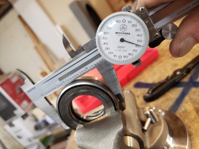
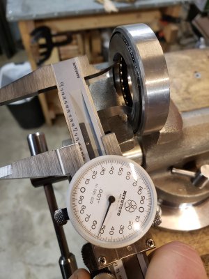
I got a package, and it did not disappoint! Here is a quick update, and some photos, I've got a ton more photos and a detailed update coming this weekend, but for now here's the short version.
The cross slide looks like it will work out great, but I can't work on it right now because I have an awkward non-round part currently dialed in on the 4jaw.
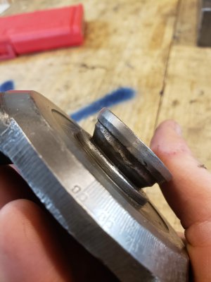
My spindle does have the the pin in the location of the spacer and the bearing I got does not have a slot/keyway for it. I did a bit of looking around the internet for more info about the bearing (while THM was down). Some people say that Atlas sold them with either a spacer/plain-bearing or the ball thrust bearing. Most convincing part is the pic of their spacer that is identical to mine.
https://groups.io/g/atlas-craftsman/topic/how_do_you_oil_the_thrust/11253514?p=Created,,,20,1,0,0
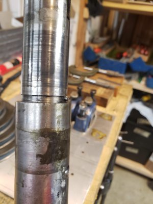
The bearing is 1/8" thicker than my original spacer, but I don't feel like shoving the spindle up 1/8" will be a problem, aside from the fact that the detent in spindle is where it is, so the cone pulley will also be pushed forward. I think it is going to cause a interference with index pin that goes into the face of the pulley, so I'll probably have to remove it. Other than that I just drilled a detent into the counter shaft for the cone pulley there, because the flat was all marred up and the set screw wasn't holding well. So the pulleys will be 1/8" out of alignment. I'll see how bad it looks when I get it together, and I might have to dill another detent further down rotated either 90 or 180 degrees from the current flat/detent.
Either way let me know what you guys think the best way to get the ball bearing onto my spindle is. I'm determined to make it work, and I would really like to not have to saw/grind off the pin. A method for pulling it out would be great, I tried grabbing it with pliers and it is pretty soft. Other than that maybe grinding a slot in the bearing, but that just feels wrong although without some better options that's where I'm leaning. Open to ideas, let me know!
The cross slide looks like it will work out great, but I can't work on it right now because I have an awkward non-round part currently dialed in on the 4jaw.
My spindle does have the the pin in the location of the spacer and the bearing I got does not have a slot/keyway for it. I did a bit of looking around the internet for more info about the bearing (while THM was down). Some people say that Atlas sold them with either a spacer/plain-bearing or the ball thrust bearing. Most convincing part is the pic of their spacer that is identical to mine.
https://groups.io/g/atlas-craftsman/topic/how_do_you_oil_the_thrust/11253514?p=Created,,,20,1,0,0
The bearing is 1/8" thicker than my original spacer, but I don't feel like shoving the spindle up 1/8" will be a problem, aside from the fact that the detent in spindle is where it is, so the cone pulley will also be pushed forward. I think it is going to cause a interference with index pin that goes into the face of the pulley, so I'll probably have to remove it. Other than that I just drilled a detent into the counter shaft for the cone pulley there, because the flat was all marred up and the set screw wasn't holding well. So the pulleys will be 1/8" out of alignment. I'll see how bad it looks when I get it together, and I might have to dill another detent further down rotated either 90 or 180 degrees from the current flat/detent.
Either way let me know what you guys think the best way to get the ball bearing onto my spindle is. I'm determined to make it work, and I would really like to not have to saw/grind off the pin. A method for pulling it out would be great, I tried grabbing it with pliers and it is pretty soft. Other than that maybe grinding a slot in the bearing, but that just feels wrong although without some better options that's where I'm leaning. Open to ideas, let me know!
Attachments

- Joined
- Dec 25, 2011
- Messages
- 10,511
None of the parts lists over the years ever showed a spacer instead of the ball thrust bearing. So I think it is like the mistaken rumor floating around the Internet that early model 618's had 1"-8 instead of 1"-10 spindle nose threads. Easily disproved by looking at the first Atlas catalog that included the 6". But some people just can't tell the difference between a 618 and a 101,07301.
Back to the thrust bearing, we have been hearing reports that the ball thrust bearing currently being sold by Clausing is thicker than the original. If you have no plan to purchase and install the back gears, the solution to what to do about the index pin is to remove the roll pin that retains it and remove the index pin from the headstock. Rotate the index pin in your drill press vise so the the old roll pin hole is horizontal. Drill a new roll pin hole 1/8" closer to the left end of the index pin and 90 degrees from the existing one so that you can pull the index pin out farther.
To remove the locator pin from the spindle you need a slide hammer equipped with a dowel pin collet type clamp. You should be able to rent one from an equipment rental place. Alternatively, you can try drilling and tapping a puller hole in the pin. That will destroy the pin. However, if the thrust bearing that someone sold you doesn't have the slot, you can't use the pin anyway. My feeling is that a ball thrust bearing without the ID locator slot is still a big improvement over the solid spacer with one so long as you don't have back gears.
Alternative.y, you could take the ball thrust bearing to a machine shop that can do EDM machining and have them cut the slot. Assuming that they won't be cutting into the balls of course.