-
Welcome back Guest! Did you know you can mentor other members here at H-M? If not, please check out our Relaunch of Hobby Machinist Mentoring Program!
You are using an out of date browser. It may not display this or other websites correctly.
You should upgrade or use an alternative browser.
You should upgrade or use an alternative browser.
VFD Carrier Frequency?
- Thread starter Ken226
- Start date
- Joined
- Oct 11, 2016
- Messages
- 3,866
I have my 2HP Teco L510 set at 15KHz on my 2HP mill. The thing you need to know is that the duty cycle of the mill is lowered. Since I make a 3 or 4 minute cut and then take 20 minutes to do the next setup, my motor never overheats.
- Joined
- Mar 26, 2018
- Messages
- 2,724
Industrial Controls guy here....
Most VFDs should have an adjustable carrier frequency between 2kHz and 16kHz with the factory default usually being 2kHz or 4kHz.
Without going too deep into the nitty gritty of why, increasing the carrier frequency increases heating inside the IGBTs of the inverter as most of the heating occurs during the switching phase of each pulse and there are now more switches occurring per second. This means, for a given load, the VFD will run hotter.
VFDs are rated for continuous duty, so increasing the carrier frequency necessitates derating the drive power rating. There should be a table in the VFD manual to show you this.
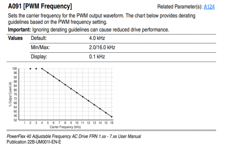
Here is an example of a derating table from a Allen Bradley PowerFlex 40 VFD:

That being said, higher carrier frequencies are necessary in many applications, especially in office HVAC, elevators, and other places where people are in a non factory setting.
For you, pick what is most comfortable and understand that you are limiting the power output on your VFD which may not be an issue.
Most VFDs should have an adjustable carrier frequency between 2kHz and 16kHz with the factory default usually being 2kHz or 4kHz.
Without going too deep into the nitty gritty of why, increasing the carrier frequency increases heating inside the IGBTs of the inverter as most of the heating occurs during the switching phase of each pulse and there are now more switches occurring per second. This means, for a given load, the VFD will run hotter.
VFDs are rated for continuous duty, so increasing the carrier frequency necessitates derating the drive power rating. There should be a table in the VFD manual to show you this.
Here is an example of a derating table from a Allen Bradley PowerFlex 40 VFD:

That being said, higher carrier frequencies are necessary in many applications, especially in office HVAC, elevators, and other places where people are in a non factory setting.
For you, pick what is most comfortable and understand that you are limiting the power output on your VFD which may not be an issue.
- Joined
- Oct 11, 2016
- Messages
- 3,866
@macardoso Thanks for mentioning the IGBTs I forgot to mention them.
I just checked and I lowered my frequency from 15KHz to 8KHz a few years ago and forgot. I only get a little 'whining' at output frequencies of 13 Hz or less - which is to be expected. My motor is not inverter rated - a standard 'pancake' motor found on most BPs and BP clones.
I just checked and I lowered my frequency from 15KHz to 8KHz a few years ago and forgot. I only get a little 'whining' at output frequencies of 13 Hz or less - which is to be expected. My motor is not inverter rated - a standard 'pancake' motor found on most BPs and BP clones.
- Joined
- Feb 25, 2021
- Messages
- 3,130
Correction: Carrier frequency drop on overheat is an option, which is disabled by default. I enabled it on mine.Note that the L510 will automatically temporarily lower the carrier frequency if they start overheating. It’s unlikely, but just be aware that if the whine comes back, that is what is happening.
- Joined
- Jan 6, 2017
- Messages
- 1,214
Industrial Controls guy here....
Most VFDs should have an adjustable carrier frequency between 2kHz and 16kHz with the factory default usually being 2kHz or 4kHz.
Without going too deep into the nitty gritty of why, increasing the carrier frequency increases heating inside the IGBTs of the inverter as most of the heating occurs during the switching phase of each pulse and there are now more switches occurring per second. This means, for a given load, the VFD will run hotter.
VFDs are rated for continuous duty, so increasing the carrier frequency necessitates derating the drive power rating. There should be a table in the VFD manual to show you this.
Here is an example of a derating table from a Allen Bradley PowerFlex 40 VFD:
View attachment 364916
That being said, higher carrier frequencies are necessary in many applications, especially in office HVAC, elevators, and other places where people are in a non factory setting.
For you, pick what is most comfortable and understand that you are limiting the power output on your VFD which may not be an issue.
Thanks for that info.
Will heatsinking the VFD help at all? My VFD is mounted to a 1/2" thick, 5"x7" solid copper plate, inside the lathe's left stand pedestal, with plenty of airflow through a vented panel on the lower left side, and up through another vented panel on the upper rear of the pedestal.
Here's the chart from my manual:

According to my chart, @ the ambient temps I see here in the Pacific Northwest it looks like I'll have very little derating to worry about. About 3% at temps below 104°.
@rabler
I looked up the parameter you mentioned. Apparently, If I set parameter 11-03, to 1 it'll automatically lower the carrier frequency when It starts getting hot.
- Joined
- Mar 26, 2018
- Messages
- 2,724
VFDs are typically rated for operation when mounted to a steel subpanel in an enclosure. Additional heat sinking really shouldn't do much. Forced ventilation in the cabinet would go much further although you are on your own as far as developing rating curves for additional forced ventilation.
At work we do a lot of speciality VFD applications where space is the highest concern. I've seen 500HP drives packed into cabinets sized for 25HP drives. All water cooled and not an inch of spare space left over. Kinda cool.
At work we do a lot of speciality VFD applications where space is the highest concern. I've seen 500HP drives packed into cabinets sized for 25HP drives. All water cooled and not an inch of spare space left over. Kinda cool.
- Joined
- Feb 25, 2021
- Messages
- 3,130
I have my 2HP Teco L510 set at 15KHz on my 2HP mill. The thing you need to know is that the duty cycle of the mill is lowered. Since I make a 3 or 4 minute cut and then take 20 minutes to do the next setup, my motor never overheats.
@Dabbler, the Teco derating for the carrier frequency applies to the VFD, not the motor. The VFD will attempt to estimate the motor heat based on parameter 08-05, or measure it directly if you install and enable a thermocouple, but that isn't related to the derating curve.
- Joined
- Jan 6, 2017
- Messages
- 1,214
VFDs are typically rated for operation when mounted to a steel subpanel in an enclosure. Additional heat sinking really shouldn't do much. Forced ventilation in the cabinet would go much further although you are on your own as far as developing rating curves for additional forced ventilation.
At work we do a lot of speciality VFD applications where space is the highest concern. I've seen 500HP drives packed into cabinets sized for 25HP drives. All water cooled and not an inch of spare space left over. Kinda cool.
That gives me an idea. I have some 120mm AC computer case fans sitting in a drawer from a project years ago. I could connect it to the 120v switched inputs of the solid state relay that turns on the VFD.
If I mounted one of them to a 5"x5" aluminum heatsink on the back of the same copper plate my VFD is mounted to, it would pull fresh outside air into the enclosure, through the heatsink fins. The heatsinking may not help much with the VFD, but it should add enough heat to the air to give it some lift. The hotter air would exit through the upper vent, maybe create a convection cycle and help the fan pull cool air in.
Last edited:
- Joined
- Feb 25, 2021
- Messages
- 3,130
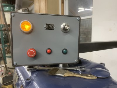
Yep. It's up to you whether you want it to start whining, or you want it to trip offline completely (quit working until it is power cycled or reset). Of course it really is unlikely you'll ever overheat it, unless you're just pushing it for fun to see how big of a chip you can cut. I actually set mine up so the Analog output pins were showing motor rated current (parameter 04-11), and then hooked those pins to a simple digital voltage display (on amazon) so I can tell what load I'm drawing. Did that to help tweak some of the overcurrent protection parameters as I was initially tripping my VFD with an overcurrent condition when engaging the clutch in higher gears.@rabler
I looked up the parameter you mentioned. Apparently, If I set parameter 11-03, to 1 it'll automatically lower the carrier frequency when It starts getting hot.
My panel doesn't compete with yours! But you can see the LEDs in the center.
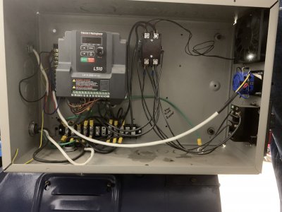
You can see my enclosure with a fan on the right.


edited to add:
The analog output can drive 0 to 10volts. I adjusted the scaling parameters so that it reads 7.5 volts at 100% motor current. 10volts would correspond to 133% rated current for the motor. I just remember those numbers.
Last edited:

